How to remove a reverse osmosis system comes down to one variable more than any other: whether the train is coming back into service, and when. That answer decides whether the job is an element change-out, a temporary lay-up, a decommissioning in place, or a full skid removal. From there the sequence is fixed. Flush the feed and concentrate side at low pressure until concentrate conductivity returns to feedwater conductivity, isolate and verify zero energy, then drain and push elements out in the direction of feed flow. The pipework left behind and the elements taken out each need a decision before the crew leaves site.
Element Change-Out, Lay-Up, or Full Removal
Removing an industrial RO system can mean four different jobs, and which one applies depends on whether the train returns to service and how much hardware stays in the frame. Treating them as one procedure is where removal plans go wrong. Each leaves behind a different restart cost.
| Work scope | What comes out | What has to be rebuilt to restart | Typical trigger |
|---|---|---|---|
| Element change-out | Elements and their seals; vessels, endplates and piping stay | Shim stack, O-rings, brine seals, start-up flush, new baseline | Performance no longer recoverable by cleaning |
| Temporary lay-up | Nothing; the train is flushed, preserved and isolated | Preservative flush-out and a slow repressurization | Shutdown with a known restart date |
| Decommissioning in place | Elements, endplates, instruments, sometimes branch pipework; frame and vessels stay | Re-commissioning of a stripped train | The train is not returning, but the footprint stays |
| Full skid removal | Skid, vessels, pumps, piping, electrical and ancillaries | Effectively a new installation | Relocation, or the footprint is being reclaimed |
Full skid removal also brings in rigging, electrical isolation at the MCC, chemical line drain-down and waste permitting. Those belong to a lift plan and a demolition method statement, not to a membrane procedure. What follows covers the first three scopes and the element-handling part of the fourth.
A bypass is often proposed as the cheap version of removal, and for a short outage it is. Over a longer one the arithmetic changes. A bypassed RO branch tied to a live header holds standing water with no crossflow to scour it, and where temperature and nutrients allow, that raises microbiological growth risk on elements that were healthy when the valve closed. The saving can return as a cleaning job.
Worth saying plainly, because it cuts against selling replacement elements: leaving elements in place under preservation is often cheaper and lower-risk than pulling them. Whether that applies to your train is not a calendar question. Check five things:
- What the element and vessel manuals permit for a shutdown of the expected length
- Whether preservative can reach every vessel and the liquid seal can be held
- Whether freezing or air ingress is credible at the site
- What the contamination history looks like
- Whether other mechanical work on the frame would disturb closed vessels anyway
When the removal date comes from a construction schedule instead of a return-to-service date, the usual result is that elements come out with no preservation plan agreed, then sit in opened bags until somebody finds them.
What to Record Before You Remove a Reverse Osmosis System
Baseline operating data has to be captured before you remove a reverse osmosis system, and how much of it matters depends on whether the elements are being scrapped or investigated afterward. Once a stack is out of the vessels, none of it can be reconstructed from the hardware.
The record set is small. Pull all of it while the train is still assembled:
- Normalized permeate flow
- Normalized salt passage
- Stage-to-stage differential pressure
- Feed, permeate and concentrate pressures
- Feed, permeate and concentrate conductivities
- Feedwater temperature
- Dates and chemistry of the last few cleanings
- Per-vessel permeate conductivity, where vessels can be sampled individually
Per-vessel conductivity identifies an anomalous vessel and can point to an internal seal or element problem, but it does not localize to a position in the stack. Permeate probing, conductivity profiling or single-element testing is what does that.
Vessel-level attribution has a shelf life, and that is easy to miss. It holds only while the mapping between reading and hardware survives the removal. Push a stack onto a pallet unlabeled, and last month’s conductivity anomaly can no longer be matched to any physical object. The question available to an autopsy drops from which vessel was off to whether anything failed at all. Labeling each element with vessel number, stage, position in the stack, removal date and observed symptom is not paperwork. It is what keeps a logsheet attached to something a technician can cut open.
Number each head assembly before it comes off and return it to the same pressure vessel, following the vessel manufacturer’s instructions. Reinstalling closures in their original positions is what makes the piping line back up on a rebuild.
Flushing, Isolating, and Verifying Zero Energy
Isolation on an RO skid covers more than the feed valve, because the pressure vessels hold stored energy on both sides and the concentrate line can siphon them empty depending on its discharge elevation.
Flush first, before the high-pressure pump is locked out. Membrane manuals call for low-pressure flushing of the feed and concentrate side, using permeate or good-quality feedwater, until concentrate conductivity comes back to feedwater conductivity. A typical flushing pressure in those manuals is around 40 psi, roughly 3 bar, with the per-element and per-vessel pressure-drop limits still governing. Confirm both figures against the manual for the elements installed.
Two published constraints explain why the flush matters during a removal. Static permeate backpressure must not exceed feed or concentrate side pressure by more than 5 psi (0.3 bar) at any time, including at shutdown. Manuals also describe permeate draw-back: when the high-pressure pump stops on an unflushed train, natural osmosis pulls permeate backward through the membrane because the concentrate side is still loaded with salt. Unless enough water volume is available on the permeate side, that can draw a vacuum or pull air in. Stop a train at full recovery and start opening drains, and the crew is working the bolts on a system still trying to move water the wrong way. Flushing to feedwater conductivity removes the gradient, so the drain sequence that follows is hydraulically neutral. Check the installed permeate-port ratings too, since vessel hardware can impose its own limit.
Then isolate and prove it. Electrical isolation alone does not cover the skid. Identify the high-pressure pump and its drive, the dosing pumps and their chemical lines, instrument air, any valve whose movement could re-admit feed, and the gravity head sitting in elevated pipework. Isolate each source, release or restrain the stored energy, and verify at the gauges instead of assuming the valves did their job. Where more than one trade is working, run it under a group lock-out. This is a description of what has to be true, not a procedure; the site’s approved energy-control procedure governs.
Then drain the vessels and adjacent pipework. If the concentrate line ends below the level of the pressure vessels, an air break is needed above the highest vessel, or the vessels can siphon themselves dry through it.
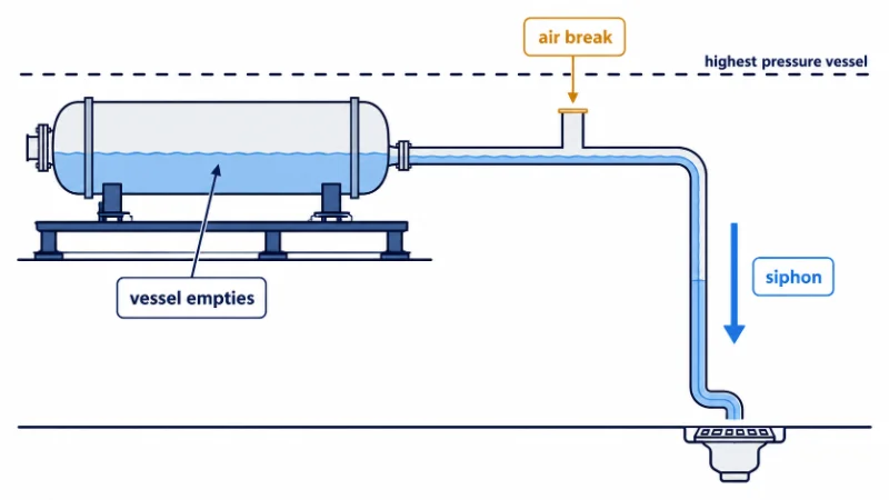
The siphon risk matters most in the case that looks safest. Take a partial removal, where the piping is opened this week and the elements come out next week. That is the configuration most likely to dry out a set of elements, because the vessels can empty through the line the crew just disconnected. Full removals are, in this narrow sense, gentler on the membranes than staged ones.
Unloading Elements from the Pressure Vessels
Element unloading runs in the direction of feed flow, and the force required varies across the train depending on service history, brine seal condition and the state of the vessel bore.
- Disconnect the hard plumbing at both ends of the vessel and tag every removed item for return to the same location.
- Remove the head assemblies from both ends, following the vessel manufacturer’s closure procedure for that model.
- Push the elements out from the feed end, in the same direction feedwater flows, one element at a time.
- Support each element as it clears the vessel. For full-size industrial elements, use two operators or an engineered handling aid, subject to the site’s manual-handling assessment.
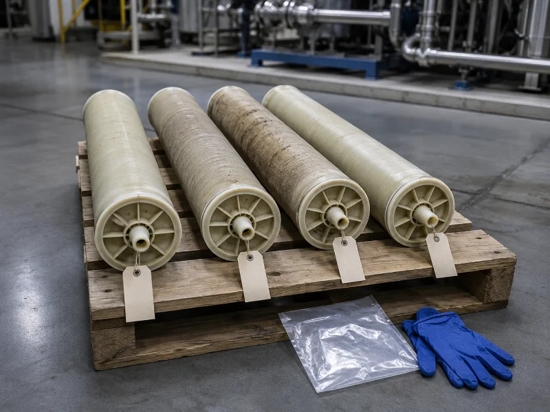
- Label everything as it comes out. Set each element down on a clean surface in stack order.
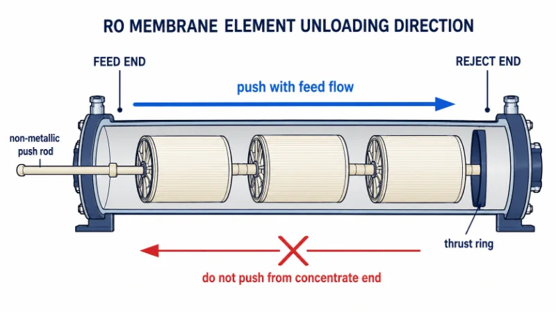
Do not push against feed direction. That is the direction the manuals give, on the grounds that the vessel thrust ring sits at the reject end only, so load applied from the concentrate side has nothing behind the elements to react against. Whether a reverse push actually telescopes an element depends on the thrust device and interconnector arrangement, which differs between vessels. Treat the published direction as the requirement and do not deviate unless the installed vessel and element manuals permit it.
Use a non-metallic pusher for a related reason. A steel bar concentrates load on the permeate tube and the anti-telescoping device, and it will score the vessel bore on the way through.
Resistance is not evenly distributed across a train, and position does not predict it. If the pushing force rises unexpectedly, stop and inspect the vessel and the element arrangement instead of adding leverage.
Preservation, Waste Classification, and the Pipework Left Behind
Removed elements and the pipework they came out of degrade on separate clocks, and how long either can sit unattended depends on ambient conditions and whether the branch still holds standing water.
For RO membrane elements, manuals specify a preservation solution of roughly 1% food-grade sodium metabisulfite, non-cobalt-activated, made up in RO or NF permeate. Soak the element vertically for about an hour so trapped air escapes, drain it, then seal it in an oxygen-barrier bag without filling the bag with solution. Label the element and the solution on the outside. Inspect at the frequency the element manufacturer specifies, typically every three months, and re-preserve if the solution is cloudy or the pH has fallen. A pH of 3 or below requires re-preservation. Preservative handling calls for gloves, sleeves and eye protection.
An element that has dried after use may lose water permeability irreversibly. Drying is a risk, not a verdict. Manuals publish re-wetting procedures, including alcohol or propanol soaks and controlled pressurization with the permeate port closed. Quarantine a dried element, record its exposure history, and put it through the manufacturer’s re-wetting and performance test before deciding whether it is scrap.
Preserving a used element is also not the same operation as storing a new one. A factory-preserved element enters the bag clean, with the preservative facing nothing but time. An element pulled from a fouled train enters carrying organic and biological load, and bisulfite is a consumable reducing agent that such a load can draw down faster. Plan around that difference; do not legislate a hold time for used stock. Inspect and re-preserve at the manufacturer’s frequency, and confirm serviceability by inspection or performance test before treating anything as a spare. Where the train could not be cleaned before removal, classify the elements as condition-unknown, not as reusable spares. Which cleaning chemistry a fouled element would need is a separate call driven by foulant identification, and it belongs to the industrial RO cleaning procedure.
Waste classification depends on what came out of the vessel with the element, not on the element itself. Characterize the retained liquid and the deposited foulant before assigning a waste code, since preservative residue, heavy metals, pharmaceutical actives or process contaminants carried in from the feed can all change it. Local regulation and the site permit decide the rest.
Check the storage temperature window against the sheet for the model in the vessels. Published limits differ at the low end between manufacturers.
For the pipework, decide at removal time whether the branch is blanked at the header or left as a capped stub. A stub tied into a live header with no flow through it is a dead leg holding water at process temperature. On hygienic, food or pharmaceutical permeate loops, the acceptable branch length and the required removal method come from the hygienic piping standard applicable to that plant, which is a question for the process team before the stub is left in place. Blanking at the header costs an outage window now and closes the question.
Where RO Removals Go Wrong, and What to Confirm First
The variable to settle before you remove a reverse osmosis system is the return-to-service date, because it sets the scope every other decision is priced against. The second is the physical removal boundary: what stays in the frame. Those two come first because the rest is downstream of them. The lifting plan, the electrical isolation boundary, the chemical line drain-down, the waste classification and the contractor lock-out interface are engineered work packages in their own right, and each is scoped by those two answers. Fix the scope late and the packages get rewritten late, which is where removal schedules break.
Where removals unravel is rarely the mechanical work. It is a train stopped at full recovery and opened before it was flushed, or elements pulled on a date driven by a contractor’s programme with no restart date agreed on paper. Both are avoidable at no cost by settling the sequence a week earlier. What a generic sequence cannot settle is anything depending on the specific hardware installed, which is why, on industrial RO systems, we verify closure type, element model and the site’s concentrate discharge elevation against the as-built condition before a removal method statement is issued.
Three answers can be pulled this week, and each closes a decision that gets expensive once the vessels are open. Pull the last 30 days of normalized permeate flow, stage differential pressure and per-vessel permeate conductivity off the historian while the elements are still in position and still mapped. Get the return-to-service date in writing, or a written statement that there is not one. Then walk the line and check where the concentrate discharge sits relative to the top of the pressure vessels. That elevation decides whether draining needs an air break or just an open valve.
FAQ
No. A point-of-use system is a plumbing job: close the feed valve, drain the tank through the faucet, release the quick-connect tubing, cap the drain saddle and plug the sink hole. There are no pressure vessels, no preservation decision and no lock-out boundary. This procedure assumes an industrial train with spiral-wound elements in pressure vessels.
Isolating one RO branch depends on whether it has its own valves upstream and downstream, and on whether the users it feeds can run on the alternative supply for the duration. Skids installed as part of the original build usually have isolation. Retrofits are more often tied straight into a header.
Feed-flow direction is the published requirement. Where an exception is claimed, the pressure vessel closure drawing settles it, not the element datasheet: the thrust arrangement is a property of the vessel.
Sometimes, and a test decides it. Reinstallation needs preservation from the moment of removal, intact vessel and position mapping, new O-rings and brine seals, and a performance check against that element’s own removal baseline. Without a preservation history, none of that can be reconstructed.
No fixed figure applies, which makes this a question about who is tracking the bags. An element preserved on the day of removal and inspected on schedule stays a candidate indefinitely. One with no owner and no inspection date is scrap on paper long before it is scrap in fact.
Valve handle positions at shutdown, instrument tie-in points, cable routing at the panel, and the endplate numbering once applied. Rebuild drawings are frequently out of date on trains modified in service.
Related Posts
- How Long Do Reverse Osmosis Filters Last? — the service-life variables sitting behind the change-out trigger in the scope table
- Membrane Fouling in High-Pressure RO Systems — the fouling and differential-pressure history that decides whether cleaning or removal is the right call
- Industrial Reverse Osmosis System Components — what is actually coming out, part by part, on a decommissioning in place
- Industrial Reverse Osmosis System Price — what a replacement train costs, once the removal decision has been taken
- Industrial Reverse Osmosis Pros and Cons — whether RO earns its place at all, before a rebuild is scoped