
Control Valves & Multiport Valves for Water Treatment Systems
We size and program control valves alongside every system we build, matching the sequencing brain to the media bed, tank volume, flow regime, and service-continuity requirement before the system leaves our workshop.
Filter backwash valves (3-cycle) and softener regeneration valves (5-cycle) — manual and automatic, 2–50 m³/h, CE certified, custom export supply.
Filter Backwash and Softener Regeneration Valve Cycles
The control valve’s job is not to regulate flow pressure; it is to sequence the media bed through service and regeneration in the correct order, at the correct timing, without operator intervention.
The distinction between a filter backwash valve and a softener regeneration valve is the number of stages it must execute and the media chemistry each stage handles. Every backwash cycle and every softener regeneration sequence begins and ends with this component, so the cycle program is treated as part of the system design rather than a site adjustment after installation. The valve determines when each stage fires, how long it holds, and what the media bed experiences at every transition.
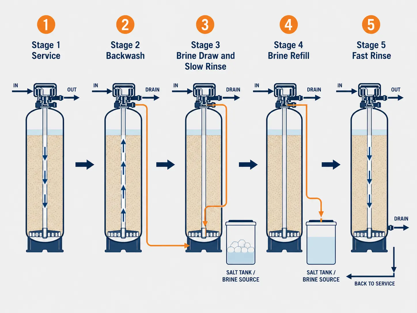
Filter Backwash Valve — 3-Cycle Sequence
1. Service — Treated water flows through the media bed in normal service direction until a time-based or volume-based regeneration trigger fires.
2. Backwash — Flow reverses upward through the bed, expanding the media by typically 30–50% and flushing trapped particulates to drain. Typical stage duration: 3–10 minutes.
3. Fast Rinse — Flow resumes in service direction at high velocity to compact and reclassify the media bed before the valve returns to service.
Softener Regeneration Valve — 5-Cycle Sequence
1. Service — Hardness ions are exchanged onto the resin bed while the valve monitors elapsed time or treated-water volume.
2. Backwash — Reverse flow loosens compacted fines and removes iron or sediment deposits accumulated during service.
3. Brine Draw + Slow Rinse — Brine is drawn from the salt tank and passed slowly through the resin, displacing hardness ions from exchange sites.
4. Brine Refill — Fresh water refills the brine tank to dissolve salt for the next regeneration cycle while previous rinse water drains.
5. Fast Rinse — Treated water rinses residual brine and confirms the bed has returned to full capacity before service resumes.
When the Backwash Interval Is Too Short
Iron deposits compact the resin rather than flushing out. The resin gradually becomes fouled, ion exchange capacity drops, and the system delivers progressively harder water before the next regeneration. Cycle timing is the first parameter we set when sizing a new softener system.
Manual vs Automatic Control Valves for Filters and Softeners
Control valves divide along two decision axes: function type and operation mode. The right combination depends on flow variability, power availability, operator presence, and service-continuity requirement.
Operator-Initiated 3-Cycle Backwash
Typical flow: 2–10 m³/h. No power required. Use when an operator is present at scheduled intervals and power is unavailable or unreliable.
Programmed 3-Cycle Backwash
Typical flow: 2–50 m³/h. Use for continuous-duty pre-treatment trains and RO feed systems where unattended operation is required.
Operator-Stepped 5-Cycle Regeneration
Typical flow: 2–10 m³/h. Use for low-throughput or power-unreliable installations where operator presence at each cycle is feasible.
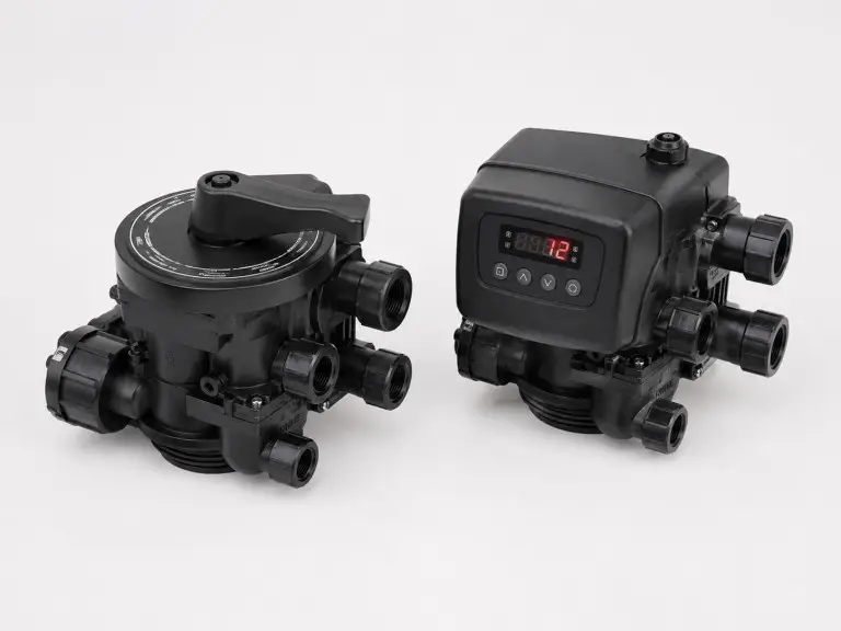
Programmable Regeneration Control
Typical flow: 2–50 m³/h. Control mode selection determines reliability: time-based, flow-metered, or dual time + flow.
| Control Mode | Trigger Logic | Best For | Risk If Misapplied |
|---|---|---|---|
| Time-based | Fixed schedule regardless of volume | Consistent daily throughput (±15%) | Resin exhaustion on heavy days; over-regeneration on light days |
| Flow-metered | Regenerates after set treated volume | Variable demand, reliable power and flow meter | Missed regeneration if meter fails or power drops |
| Dual time + flow | Whichever trigger fires first | Variable industrial loads, shift production | This is our default specification for industrial softeners |
For industrial installations where daily flow varies across production shifts, we configure dual time + flow valves as the standard specification. Time-only programming misses volume overruns and can leave resin under-regenerated by the end of a heavy production shift, delivering hardness to downstream equipment exactly when production demand is highest. Flow-only triggering is useful when metering is stable, but a meter fault or power interruption can still skip a necessary regeneration event; the dual trigger gives the project a time safety limit and a volume safety limit in one control program.
Specifications Reference
Use this table as a pre-inquiry reference. Final body material, pressure rating, and connection configuration are confirmed after we review media type, flow rate, water chemistry, and installation constraints.
| Parameter | Specification |
|---|---|
| Valve function — filter | 3-cycle: service / backwash / fast rinse |
| Valve function — softener | 5-cycle: service / backwash / brine + slow rinse / brine refill / fast rinse |
| Control modes | Manual; automatic time-based; automatic flow-metered; dual time + flow |
| Flow rate coverage | 2–50 m³/h, typical multiport valve product line range |
| Inlet/outlet connection | ¾”, 1″, 1.5″, 2″ threaded; flanged for larger configurations |
| Tank connection thread | 2.5″ male thread standard; 4″ male thread for larger tanks |
| Body material — standard | ABS reinforced with 10% glass fiber, corrosion-resistant and heat-resistant¹ |
| Body material — high-pressure / aggressive media | Stainless steel or brass |
| Working pressure | Typically 0.2–0.8 MPa for standard configurations¹ |
| Mounting style | Top mount standard; side mount for space-constrained installations |
| Bypass configuration | Integral bypass for smaller systems; external bypass for industrial-scale layouts |
| Tank configuration | Single tank; duplex alternating for two-tank continuous 24/7 service |
| Display / controller | LED or LCD controller on automatic models |
| Certifications | CE |
¹ Body material and working pressure reflect standard configurations commonly supplied in this product class. High-pressure or aggressive-media applications use stainless steel or brass body configurations with different pressure ratings, and all specifications are model-dependent; actual values are confirmed during engineering review.
NSF/ANSI 61 (drinking water contact) and NSF/ANSI 44 (water softeners) are not claimed for these valves unless explicitly stated in the order documentation. Buyers supplying potable water systems in regulated markets should confirm applicable certification requirements at inquiry.
How to Size a Multiport Control Valve
Valve selection depends on four engineering decisions: valve flow rating, control mode, single-tank versus duplex continuity, and bypass configuration.
Match Valve Flow Rating to Tank Diameter
Control valve connection size must match actual flow rate, which is determined by tank cross-sectional area and media bed superficial velocity. Standard references are V = 20 m/h for softening and V = 10 m/h for filtration.
A 300 mm diameter softener tank has a cross-section of about 0.07 m². At V = 20 m/h, maximum service flow is roughly 1.4 m³/h, so a 1″ or 1.5″ valve is the correct selection.
A 500 mm softener tank has a cross-section of about 0.196 m² and maximum softening flow near 3.9 m³/h; a 1.5″ valve is appropriate. A 2″ valve may pass the service flow, but unless the backwash flow rate, drain line sizing, and programmed backwash duration are matched to tank cross-section and media type, the bed may not reach the required expansion velocity for effective flushing.
Undersizing is equally damaging: a 1″ valve on a system running 10 m³/h creates excessive pressure drop, degrades downstream equipment performance, and can cause channeling through the bed. Oversizing damages the opposite side of the operating window: the valve passes service flow, but the backwash stage no longer reaches the velocity needed to lift the bed and flush compacted fines. We size valve connection as part of the same engineering step as tank diameter, not as a separate procurement decision after the tank has been specified.
Select the Control Mode
| Operating Condition | Recommended Control Mode |
|---|---|
| Consistent daily production volume (±15%) | Time-based automatic |
| Variable demand, reliable power | Flow-metered volume trigger |
| Variable demand, variable power, industrial load | Dual time + flow |
| No reliable electrical power | Manual |
| 24/7 continuous service required | Duplex alternating with automatic |
For industrial installations where daily flow varies across production shifts, dual time + flow prevents both resin exhaustion and schedule-driven over-regeneration.
Decide Single Tank or Duplex Alternating
A single-tank softener goes offline during regeneration, typically 1.5–2 hours. For most commercial and light-industrial installations, this downtime is acceptable if scheduled during low-demand periods.
Hospitals, boiler feed systems running continuous steam generation, electrodeposition paint lines, and 24/7 pharmaceutical process water require duplex alternating. When Tank A enters regeneration, the valve bank switches service to Tank B with no service gap.
For boiler feed water treatment applications, we routinely recommend duplex when boiler production cannot tolerate a two-hour softened-water interruption.
Specify the Bypass Before Shipment
A bypass valve lets the system be taken offline for valve service or media replacement while the pipeline continues to supply untreated water downstream. Without a properly sized bypass, every valve service event requires a full system shutdown.
Smaller systems typically use an integral three-position bypass built into the valve body. Larger industrial systems use an external bypass manifold with separate isolation valves, allowing independent isolation of each treatment-train component.
We specify the bypass configuration as part of the system design, not as a site-installed afterthought.
Applications: Softeners, Media Filters, and RO Pre-Treatment
Control valves we supply are engineered to the system they serve. We do not supply valves as catalog items disconnected from the treatment train they will drive.
Ion Exchange Water Softeners
Our single-valve single-tank, single-valve double-tank, and multi-tank softener systems leave the factory with the regeneration valve mounted, plumbed, and programmed to resin volume, tank geometry, and buyer-provided inlet hardness. The valve is not a loose accessory shipped separately; it is commissioned as part of the system before dispatch. Duplex alternating control valve arrangements are available for continuous-service softener configurations where regeneration must not interrupt softened-water supply.
Pre-Treatment Media Filter Trains
Filter backwash control valves serve multimedia filters, activated carbon filters, quartz sand filters, and iron and manganese removal filters. Each media type has a different optimal backwash velocity and backwash duration. The valve program for a quartz sand filter running 10 m/h filtration velocity is different from a dense garnet bed or manganese greensand iron removal filter, so we configure timing before shipment based on media type, bed depth, and operating flow confirmed during engineering review.
RO Pre-Treatment Train Backwash
In a complete RO system, the pre-treatment train ahead of the membrane in reverse osmosis typically includes multiple filter stages – sediment, multimedia, and activated carbon – each controlled by a dedicated backwash valve or shared valve manifold depending on the system design.
Backwash cycles must be coordinated so they do not fire simultaneously, depressurize the pre-treatment train, and expose the membrane housings to feed pressure excursions. We design the backwash sequencing logic as part of the full system engineering, not as individual valve programs that happen to coexist in the same skid.
For high-purity deionization water system applications, the pre-treatment filter valve program is configured to minimize backwash water waste and prevent any microbial growth window caused by a media bed sitting in stagnant water between infrequent cycles.
The pump for ro system downstream of the pre-treatment train is sensitive to feed pressure variation during pre-treatment backwash events. When we design a complete RO system, the backwash valve controller is integrated with pump logic to prevent the pump from experiencing a sudden feed pressure drop during a backwash stage transition.
Final compliance must be confirmed against the user’s process specification, validation protocol, and applicable local standard.
Five Specification Mistakes That Change the Outcome
These are the five most common control valve specification errors we correct before production because they change media cleaning, resin exhaustion, downtime, or total project cost.
Valve Sized from Pipeline Diameter
The pipe connecting to the valve may be 2″ nominal because the site’s distribution header is 2″, but if the softener operates at 1.5 m³/h, a 2″ valve is grossly oversized. Valve selection must follow the system flow calculation, not the pipe schedule, because an oversized valve on a small tank reduces backwash flow velocity below the bed expansion threshold.
Time-Only Programming on Shift Production
A facility running two production shifts Monday to Friday and a short Saturday shift processes substantially more water on weekdays than weekends. A time-only valve regenerates at fixed intervals regardless of throughput, so the resin may be exhausted by the end of a heavy production day before the scheduled cycle fires. The result is hardness breakthrough to process equipment or boiler feed, usually detected only after scale damage has occurred.
Backwash Drain Line Undersized
The drain line carrying backwash water to waste must pass the full backwash flow without creating back pressure. A drain line that is undersized or routed with excessive head loss reduces effective backwash expansion below design velocity, leaving compacted fines in the bed. This is rarely caught during commissioning because the tank appears to backwash, but the fines remain.
No Bypass on a High-Continuity Site
A hospital or food processing facility that installs a single-tank softener with no bypass faces a poor choice during the first valve service event: shut down softened-water supply to the process or defer service until a planned shutdown. Deferring valve service leads to valve wear that is not caught until failure occurs during service, often in the middle of a production run.
Duplex Treated as a Performance Upgrade
Duplex systems cost more than single-tank systems, but the correct specification trigger is not “more flow”; it is “zero-downtime service continuity during regeneration.” Specifying duplex for a hotel laundry operation that can schedule overnight regeneration is unnecessary cost. Not specifying duplex for continuous boiler feed is an engineering deficiency that shows up as process interruption.
Custom Supply for System Manufacturers
We supply control valves as standalone components for water treatment equipment manufacturers and factory-fitted, programmed valves inside complete Hiju systems for direct export.
CE Documentation
CE documentation and factory test records are available for applicable valve models. Please confirm destination market, controller type, and model number at inquiry so we can provide the relevant Declaration of Conformity and supporting technical documents.
OEM/ODM Branding
Valve labels, controller interface branding, and packaging can be configured to buyer specification.
Factory Scale
Our 21,000 sqm workshop staffed by 78 technicians and 28 engineers supports repeat supply programs.
Export Scope
We have exported to 20+ countries and regions since 2016 across Southeast Asia, the Middle East, Africa, South America, and Central Asia.
ISO 9001 Quality System
Buyers sourcing components for their own CE-marked or ISO-registered systems can access our quality documentation.
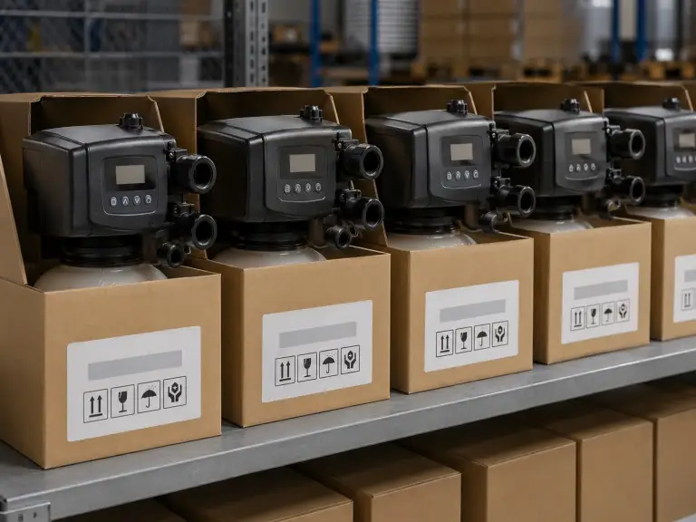
Buyers sourcing first-time orders can request sample units for qualification testing before committing to a production volume. Preferred contact: WhatsApp, email, or our online inquiry form. For custom supply programs, we confirm label files, controller interface language, packaging marks, carton layout, CE documentation, and factory test record requirements before the first production batch so the valve supply package fits the buyer’s own export documentation workflow.
Valve Review Checklist
Our engineers confirm tank cross-section, media velocity, and continuity requirement before selecting connection size, control mode, and bypass configuration.
- Valve function — filter backwash (3-cycle) or softener regeneration (5-cycle)
- Tank diameter and media type (resin / quartz sand / activated carbon / greensand)
- Required service flow rate (m³/h) and daily throughput
- Control mode preference — manual, time-based, flow-metered, or dual time + flow
- Tank configuration — single tank or duplex alternating (24/7 service)
- Body material — ABS reinforced, stainless steel, or brass (per pressure/media)
- Power supply — voltage and frequency; 110V / 220V / 380V; 50/60 Hz
- Custom labeling scope — label files, controller interface language, packaging marks
- Destination country — for CE documentation and export compliance review