
Non-Negative Pressure Water Supply Equipment
Connects directly to the municipal main — captures existing inlet pressure and adds only the differential your building requires. ISO 9001 certified. CE compliance documentation (covering applicable directives for electrical, mechanical, and pressure equipment) supplied per destination requirements. ASME pressure-vessel documentation available on request for the steady-flow tank where project specification requires an ASME-stamped vessel. Exported to 20+ countries.
We build these systems for projects where the municipal supply already delivers usable pressure. Non-negative pressure water supply equipment, formally known as pipe network superimposed pressure supply equipment, connects directly to the municipal main and uses what the utility already delivers instead of pumping from a zero-inlet baseline.
How Non-Negative Pressure Equipment Works
Non-negative pressure water supply systems operate across three distinct modes. Which mode runs at any given moment depends on one variable: how much pressure the municipal main is delivering relative to what downstream demand requires. Understanding the trigger condition for each mode is the foundation of competent system selection.
The system monitors municipal inlet pressure continuously. When inlet pressure satisfies outlet demand, bypass mode runs at zero pump energy. When inlet pressure falls short, the VFD pump group engages and modulates speed to close the differential. When municipal supply is fully interrupted, the sealed steady-flow tank provides a limited reserve — measured in minutes, not hours — while the vacuum eliminator prevents negative pressure from forming in the public main.
The practical result is that pumps run only when and as fast as they need to. In a mid-rise hotel with stable municipal supply, bypass mode covers a substantial share of total daily volume. Average pump energy per cubic metre delivered is substantially lower than a traditional tank-and-pump system that must pump from zero inlet pressure on every cycle.
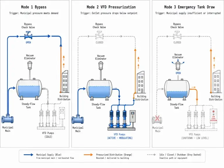
Bypass
Trigger: Municipal inlet pressure ≥ required outlet set-point.
When municipal inlet pressure at the connection point meets or exceeds the set-point outlet pressure required to serve the building, the bypass check valve opens and water flows directly to the distribution network. The VFD pumps do not run. Pump energy consumption in this mode is zero.
This mode operates more often than most buyers expect. In a mid-rise hotel with stable municipal supply, bypass mode covers a substantial share of total daily volume, especially during off-peak periods. Energy savings relative to traditional tank-and-pump configurations are project-dependent and explained primarily by bypass hours per day and reduced pump differential head; measured savings in stable-pressure projects typically fall in the 20–50% range.
VFD Pressurization
Trigger: Building demand rises until municipal pressure alone cannot maintain outlet set-point.
The frequency converter activates the VFD pump unit. Pumps start on soft start to avoid pressure spikes. The converter modulates pump speed in real time, maintaining constant outlet pressure to within ≤0.02 MPa of set-point.
Pump head required equals required outlet pressure minus current municipal inlet pressure. If inlet delivers 0.25 MPa and required outlet is 0.60 MPa, the pumps add 0.35 MPa, not 0.60 MPa from zero. Pumps are sized for differential pressure, and inlet pipe velocity must remain ≤1.2 m/s at peak demand.
Emergency Tank Draw
Trigger: Municipal supply fully interrupted.
The vacuum eliminator opens to destroy any negative pressure that would otherwise form in the system and adjacent municipal main segment. The sealed steady-flow tank provides a limited reserve, sized to a minimum of 1 minute of peak flow rate by design standard. The liquid level detector shuts pumps down at low-level threshold to prevent dry-running.
Mode 3 is a safety function, not a backup supply strategy. The reserve is measured in minutes, not hours. Supply resumes automatically when the municipal main is restored. If your project requires extended emergency supply, a steady-flow tank does not provide it.
Is This System Right for Your Project?
The decision to specify non-negative pressure equipment is conditional on municipal supply characteristics. We have seen projects choose this system on capital-cost grounds without confirming supply stability and then encounter predictable operational problems. The fit-condition review is not a formality.
For Hiju, the anti-goal is as important as the sales goal: we do not want to convert a buyer whose municipal supply is chronically interrupted. A misqualified project creates downstream engineering problems that cost more than the lost inquiry. We therefore ask for pressure data, available inlet flow, pipe diameter, and authority approval status before we treat this as the correct route.
| Condition | Fit | Engineering Consequence |
|---|---|---|
| Continuous municipal supply with sustained inlet pressure ≥0.15 MPa | Suitable | Pressure that occasionally dips but recovers quickly can still work; send utility service data and we assess the profile before selection. |
| Peak building demand falls within available inlet flow rate and inlet pipe velocity ≤1.2 m/s | Suitable | The system can superimpose pressure efficiently when the inlet pipe can sustain peak demand without excessive velocity or pressure drop. |
| Equipment room footprint is constrained and there is no space for a large reinforced-concrete open tank | Suitable | The compact factory skid eliminates the civil tank structure and recovers building space. |
| Project priority includes prevention of secondary contamination in potable water | Suitable | The fully sealed system avoids open-tank exposure to particulates, algae growth, and temperature cycling. |
| Hotels, high-rise residential, office complexes, schools, factories, and non-critical hospital wings with stable demand | Suitable | These profiles often alternate between bypass and low-speed VFD operation, which supports energy recovery from municipal pressure. |
| Municipal supply is regularly interrupted or chronically low during peak hours | Not suitable | The steady-flow tank depletes within minutes and the system shuts down. That is a design failure, not a product failure. |
| Existing inlet pipe diameter cannot sustain ≤1.2 m/s at peak demand | Not suitable until corrected | Undersized piping creates pressure drops and cavitation risk that pump capacity cannot compensate for. |
| Guaranteed zero-interruption supply is required for clean rooms, ICU circuits, hazardous processes, or fire suppression | Not suitable alone | A 1-minute steady-flow reserve cannot replace dedicated backup storage or a fire water system. |
| Local water authority approval has not been obtained | Hold specification | Direct public-main connection requires documented municipal consent before commissioning. We provide technical documentation, but approval must be secured locally. |
Uncertain Supply Profile?
If you are uncertain whether your municipal supply is stable enough, send us the utility service data before asking for a model number. We will review inlet pressure, available flow, pipe diameter, and approval status before recommending this route or a traditional tank-and-pump system.
Within our water storage and supply solutions family, this is the only product type where the municipal supply profile – not the tank size or material – determines whether to proceed at all.
Any direct municipal main connection also requires documented backflow prevention and cross-connection control measures. We include a vacuum suppressor and bypass check valve as standard; local water authority may require additional backflow preventers, inlet pressure limiters, or specific device approvals depending on jurisdiction and pipe configuration.
The suitable downstream uses include hotels, high-rise residential buildings, office complexes, schools, factories, food processing plants, and hospital non-critical water supply wings. Pharmaceutical clean rooms, certain ICU circuits, hazardous chemical process lines, and fire suppression systems require a different reserve strategy. If the supply is cut daily, the steady-flow tank will deplete within minutes; the system will shut down during exactly the condition when water is most needed.
Eight Components in the Factory-Assembled Unit
We supply these systems as factory-assembled units. Each component below is selected to its engineering function; none are optional in a compliant installation.
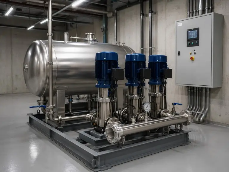
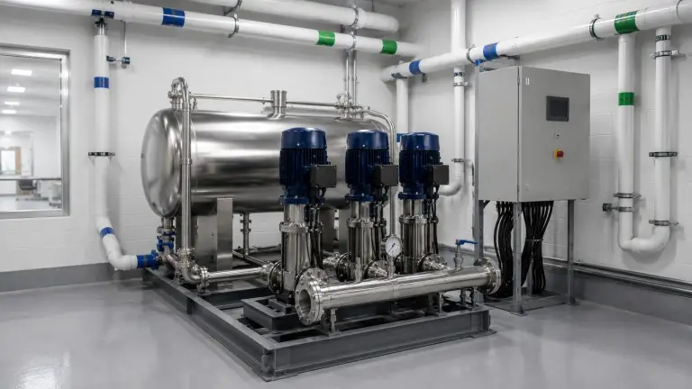
The eight components below constitute one hydraulic protection chain. They are factory-assembled at our Qingdao plant on a single skid, electrically wired to a single control cabinet, and pressure-tested as a unit before shipment.
Steady-Flow Tank
A sealed stainless steel vessel in horizontal or vertical orientation. Capacity is set at ≥1 minute of project peak flow. It buffers Mode 2 transitions and provides the limited Mode 3 emergency reserve. We manufacture it from food-grade stainless steel (SUS304 standard; SUS316L on request), the same material family used in our stainless steel water tanks.
Vacuum Suppressor / Eliminator
Prevents negative pressure forming in municipal mains when the system draws from the steady-flow tank. Without it, a partial vacuum can introduce contaminants through pipe joints and create pressure transients in adjacent infrastructure.
VFD Pump Unit
Two to five vertical multi-stage centrifugal pumps operate in parallel, with at least one standby pump mandatory. The frequency converter modulates speed from the outlet pressure sensor signal. Pumps are sized for differential pressure, not full outlet pressure.
Frequency Conversion Control Cabinet
Manages closed-loop speed regulation, pump rotation, mode transitions, and protections including soft start, overload, short circuit, overvoltage, undervoltage, phase loss, overheating, and pump stall.
Pressure Sensor
Provides real-time outlet pressure monitoring to ≤0.02 MPa control accuracy. Sensor fault or out-of-range reading triggers control cabinet alarm and standby logic pending inspection.
Remote Pressure Gauge
Gives site personnel a human-readable analog or digital pressure display on the control panel for routine daily checks and building-management handover.
Liquid Level Detector
Monitors steady-flow tank level continuously. At low-level threshold during Mode 3, it signals pump shutdown before dry-running. It also confirms refill before automatic restart.
Bypass Check Valve
Allows direct municipal flow during Mode 1 and prevents reverse flow from the building network into the municipal main, avoiding a contamination event that would trigger regulatory action.
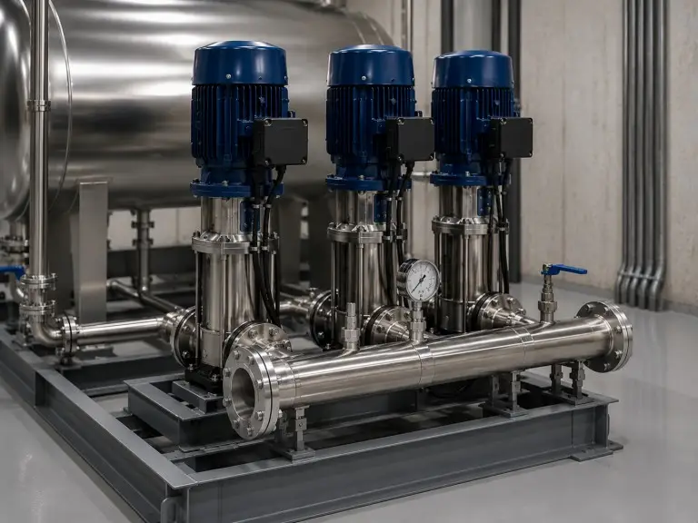
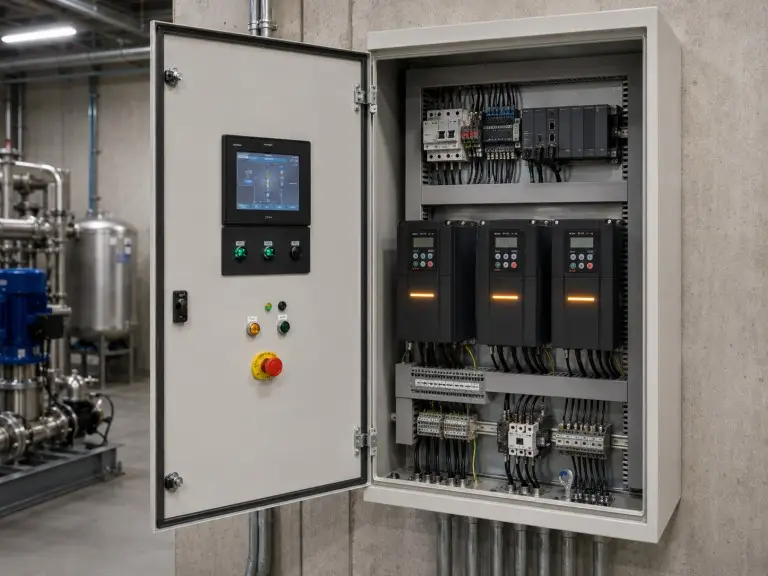
Why no component is optional
The steady-flow tank, vacuum suppressor, pump group, controls, sensor package, level detector, pressure display, and bypass check valve work as one hydraulic protection chain. Removing the vacuum suppressor risks negative pressure in the public main. Removing the standby pump compromises secondary pressurization duty. Removing the level detector exposes pumps to dry-running during Mode 3. These are not catalogue accessories; they are the minimum compliant architecture for direct-main connection.
Design Envelope and Operating Parameters
Our standard design range covers the parameters below. For projects beyond these ranges, including large industrial sites, municipal-scale infrastructure, or unusual pressure profiles, we engineer to your specification.
| Parameter | Specification |
|---|---|
| Flow range | 8-255 m³/h standard; engineered to project specification for larger systems |
| Head range | 15-259 m |
| Supply height | 10-200 m |
| Working pressure, inlet | 0.15-2.0 MPa |
| Working pressure, outlet | Up to 1.6 MPa |
| Pressure control accuracy | ≤0.02 MPa under stable operating conditions; subject to sensor range, VFD tuning, and inlet pressure fluctuation |
| Inlet pipe velocity | ≤1.2 m/s design ceiling |
| Steady-flow tank capacity | ≥1 minute peak flow rate, per design standard |
| Pump quantity | 2-5 VFD pumps in parallel; minimum 1 standby mandatory |
| Control configurations | 1-control-1 / 1-control-2 / 1-control-multi |
| Energy savings | Up to 20-50% vs traditional tank-and-pump, project-dependent |
| Protection functions | Soft start; overload; short circuit; overvoltage; undervoltage; phase loss; overheating; stall |
| Tank and wetted-part material | SUS304 standard; SUS316L available on request. Wetted-part material certificates, passivation reports, and potable-water contact compliance documentation available per project requirement. |
| Certifications | ISO 9001 / CE (applicable directives per destination); ASME pressure-vessel documentation available on request |
The values above are Hiju preliminary design targets for non-negative pressure water supply equipment. Final limits depend on inlet supply conditions, pump configuration, and project-specific engineering review. Steady-flow tank minimum volume is calculated from at least one minute of peak design flow per applicable design standard (including CJ/T 265-2016 and GB/T 26003-2010 where applicable); confirm required standard with local authority during approval.
The head range indicates pressure the standard systems can deliver to the distribution point. Suitability for a specific building depends on inlet pressure, inlet pipe diameter, and peak flow, not floor count in isolation. We calculate suitability from the parameters you provide.
A rule of thumb based only on building height is not adequate for specification. Two buildings with the same floor count can require different pump selections if one has stronger inlet pressure, a larger connection pipe, or a different peak-flow pattern. We calculate differential head from required outlet pressure minus current municipal inlet pressure, then verify inlet velocity and standby pump logic before releasing a configuration.
Typical Installation Contexts
Non-negative pressure water supply equipment suits applications where municipal supply is stable, the connection pipe is adequately sized, and the project priority includes eliminating open-tank contamination risk or recovering equipment room space.
Hotels and Commercial Buildings
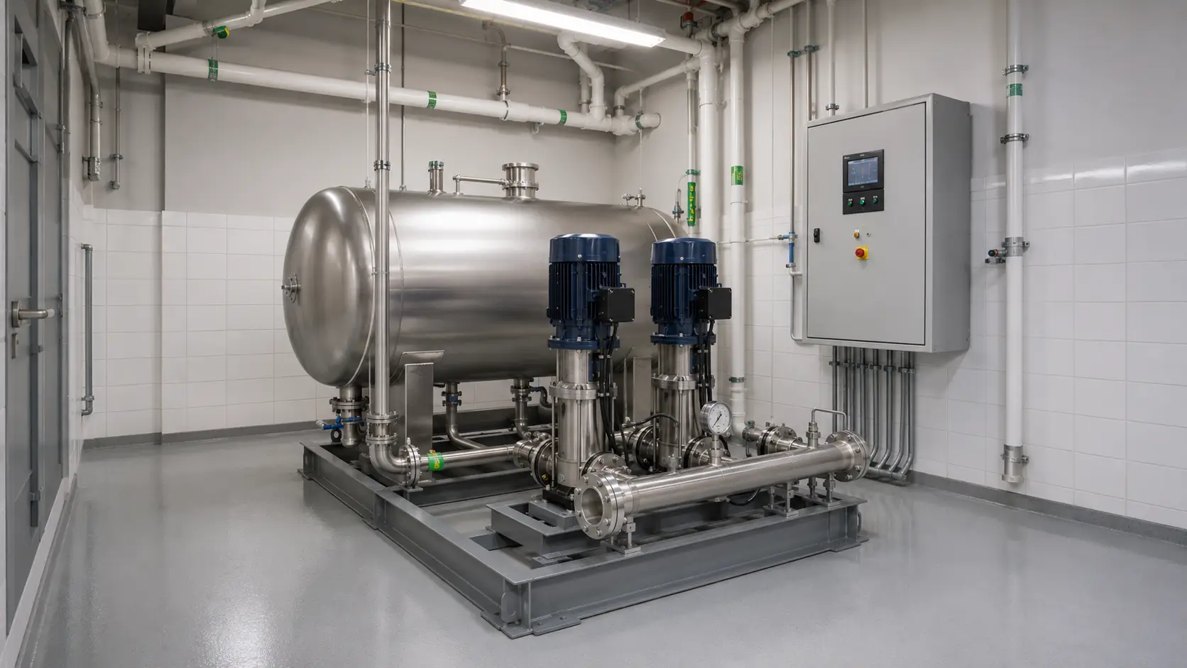
Hotels present an ideal profile. Baseline demand never reaches zero; kitchen prep, service circuits, and fan coil loops keep a continuous draw overnight. Bypass mode handles a high share of total daily volume, and average pump energy is low relative to throughput. This unit is one pressurization component within a complete building water package — we supply water filtration systems for commercial use where broader treatment integration is required.
High-Rise Residential
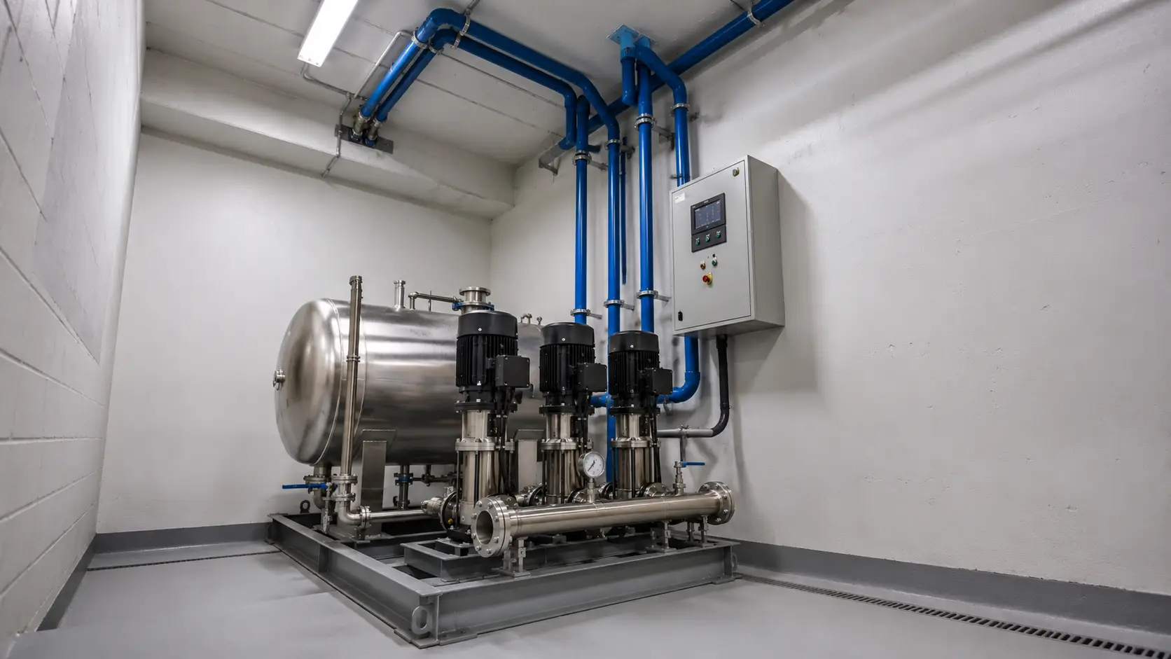
Upper floors require secondary pressurization where municipal pressure falls below fixture service pressure. Residential demand follows morning and evening peaks separated by low-demand intervals. VFD modulation handles peaks efficiently, while off-peak periods often allow bypass operation when the municipal inlet is usable.
Typical condition: stable mains pressure outside morning and evening peak draw, with upper-floor fixture pressure confirmed by hydraulic calculation.
Food Processing Plants
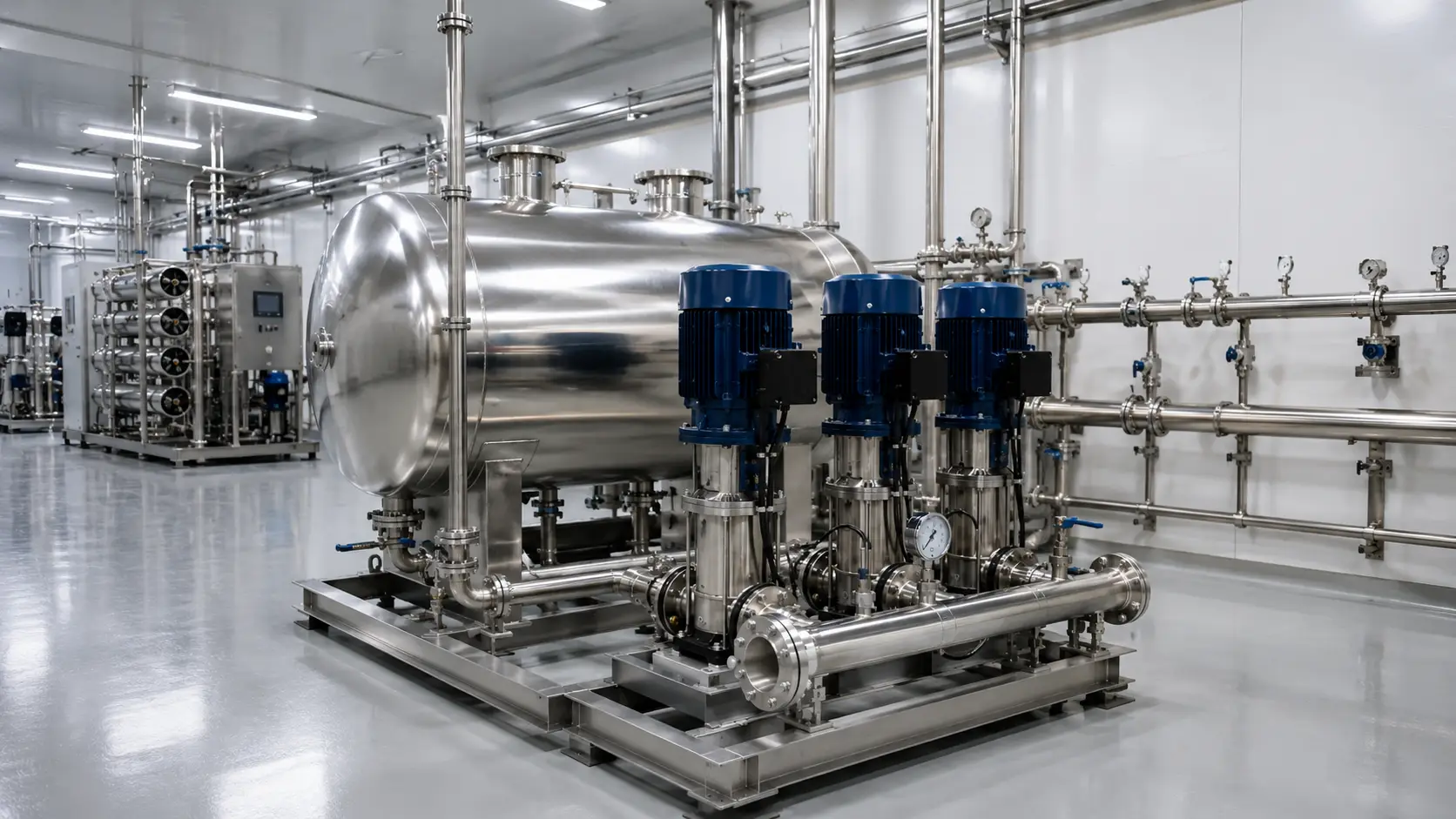
Food-grade process water supply requires sealed, contamination-controlled systems. The fully sealed configuration eliminates open-tank contact time that creates biological growth risk. This unit sits at the pressurization stage within a complete treatment train — including upstream filtration and downstream distribution — for bottled water plants and food production facilities.
Office and Commercial Parks
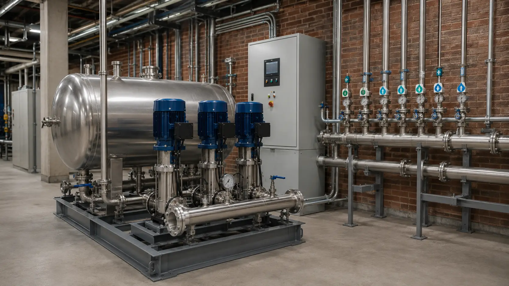
Office parks have moderate daytime demand and near-zero overnight flow. Overnight periods keep the system in bypass for extended hours, while daytime demand draws it into VFD mode at moderate pump speeds within efficient converter range.
Typical condition: business-hour demand concentrated in sanitary and pantry fixtures, with long low-flow intervals that make bypass hours valuable.
Schools and Hospitals, Non-Critical Wings
Both building types have large daytime demand and space-constrained plant rooms. The compact assembly is an advantage over a tank-based approach requiring extra civil structure. Critical-care hospital circuits require separate reserve review because a steady-flow tank cannot meet extended backup expectations.
Typical condition: domestic or utility water circuits separated from life-safety and critical-care reserve requirements.
Factories and Industrial Facilities
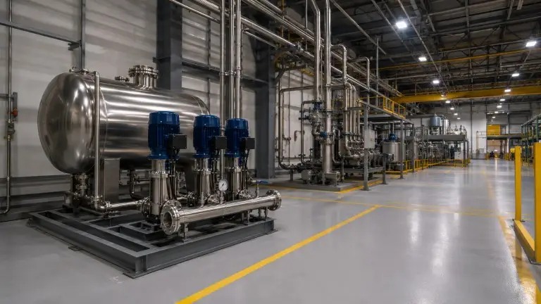
Manufacturing, electronics production, and general industrial facilities can use the system where inlet pressure is stable and continuous. The tank-free layout recovers floor area otherwise occupied by reinforced-concrete storage, which can carry direct production value beyond construction-cost reduction.
Typical condition: stable process-water demand, known peak flow, and inlet mains capacity verified before pump differential head is selected.
Final compliance must be confirmed against the user’s process specification, validation protocol, and applicable local standard.
Non-Negative Pressure vs. Traditional Tank + VFD Booster
Neither system is universally correct. Non-negative pressure suits stable municipal supply zones. Traditional tank-and-pump systems suit intermittent or chronic low-pressure zones. We ask buyers to share municipal supply data and return the recommendation based on that data, not unit margin.
| Factor | Non-Negative Pressure | Traditional Tank + VFD Booster |
|---|---|---|
| Secondary contamination | Fully sealed, no open tank | Open tank risk: algae, particulates, sediment |
| Space required | Compact equipment room only | Large reinforced-concrete tank plus dedicated pump room |
| Construction cost | Typically lower installed cost because no reinforced-concrete tank structure is required; actual saving depends on site conditions and local construction pricing. | Higher: tank structure, civil works, waterproofing |
| Energy consumption | Lower: leverages municipal inlet pressure; bypass mode runs at zero pump energy | Higher: pumps start from zero even when inlet pressure has value |
| Emergency reserve | Limited: steady-flow tank sized to ≥1 minute peak flow, not hours | 2+ days in a correctly sized storage tank |
| Regulatory requirement | Local water authority approval required before connection | Standard construction and building permits |
| Maintenance | No open-storage-tank cleaning required. Steady-flow tank, vacuum suppressor, sensors, valves, and wetted pipework require scheduled inspection and maintenance per local regulations. | Periodic tank cleaning plus pump service |
| Contamination risk during storage | Lower than open-tank storage; no open-air exposure during normal operation. Final hygiene depends on municipal water quality, backflow prevention, wetted-material compliance, and maintenance schedule. | Dependent on tank cleaning frequency and cover integrity |
The emergency reserve comparison is where buyers most often misjudge the trade-off. A steady-flow tank is a buffer, not backup supply. If 30 minutes or more of reserve is a project requirement, a tank-based or hybrid configuration is the appropriate engineering answer.
Traditional tank plus VFD booster remains the correct answer in intermittent-supply zones because its reserve can be sized in hours or days. Non-negative pressure equipment is the correct answer where the municipal main is continuous and positive, because it avoids open-tank contamination, reduces construction work, and uses inlet pressure that would otherwise be discarded. We can design a hybrid configuration when supply data suggests that direct-main operation is useful but reserve volume is still required.
Export-Ready Certification and Single-Source Supply
We are Qingdao Hiju Thermal Power Co., Ltd Our manufacturing facility covers 70,500 sqm with 21,000 sqm of dedicated workshop space. Our engineering team consists of 78 technicians and 28 engineers.
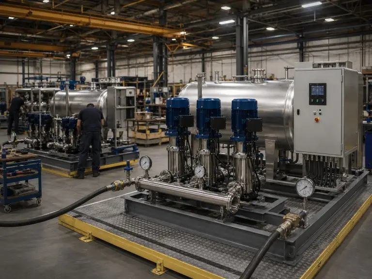
We hold ISO 9001 certification. CE compliance documentation is prepared according to applicable directives for each destination market. ASME pressure-vessel documentation is available on request for the steady-flow tank where an ASME-stamped vessel is required. In the competitive landscape for non-negative pressure water supply equipment, where visible export suppliers often do not publish international certification for this product type, our certification status is a direct differentiator for buyers sourcing into regulated construction markets in Southeast Asia, the Middle East, Africa, South America, and Central Asia.
OEM and ODM configurations are available. Our engineering team handles custom specification from hydraulic calculation through control panel interface design, not just assembly substitution. Preferred contact is WhatsApp, Email, or the online inquiry form; our engineers review project parameters and return a configuration recommendation, not a generic quotation.
Custom scope can include pump quantity, standby logic, 1-control-1, 1-control-2, or 1-control-multi cabinet configuration, interface language, voltage and frequency, alarm outputs, destination-country documentation, skid dimensions, pipe connection direction, and material requirements. For export procurement teams, the practical value is that the hydraulic calculation, fabrication, electrical control, and documentation package come from one accountable factory source.
70,500 sqm
Total factory area at Qingdao manufacturing base.
21,000 sqm
Workshop space for fabrication, assembly, and pressure testing.
ISO 9001 / CE
ISO 9001 governs our quality management system. CE documentation covers applicable electrical, mechanical, and pressure-equipment directives per destination. ASME scope is available on request.
For projects requiring both pressurization and passive storage vessels, we manufacture the complete range from the same factory. Our PE plastic water tanks serve chemical-resistant and outdoor storage applications where stainless steel is over-specified. For corrosive environments or large-volume outdoor installations, our FRP water tanks provide structural capacity with chemical resistance that metal vessels cannot match.
Quote Input Checklist
Our engineers review your municipal supply data alongside your building requirement profile. Inlet pressure, available flow, and pipe diameter determine whether this product is the correct route before we issue a configuration.
- Municipal inlet pressure profile — sustained value, peak-hour minimum, and interruption frequency
- Available inlet flow rate and inlet pipe diameter (verify ≤1.2 m/s at peak demand)
- Required outlet pressure set-point and supply height (m)
- Building peak flow rate (m³/h) and demand pattern across 24 hours
- Pump configuration preference — 1-control-1 / 1-control-2 / 1-control-multi
- Power supply — voltage and frequency: 110V, 220V, 380V; 50 or 60 Hz
- Local water authority approval status and required documentation package
- Destination country — for export certification compliance review
- OEM/ODM requirements — branding, panel interface language, packaging
Common Questions About Non-Negative Pressure Equipment
The questions below address approval, reserve limits, power outage behavior, low municipal pressure, tank calculation, and OEM configuration.