
Electrodeionization System for Industrial Ultrapure Water After RO
We manufacture and supply complete electrodeionization systems for industrial ultrapure water applications. When your project requires high-purity polishing after reverse osmosis, the sizing process covers RO permeate quality, feed conductivity, FCE, silica, CO2, target resistivity, flow rate, and application before the EDI system is specified.
What an Electrodeionization System Does in an RO+EDI Train
An electrodeionization system, also called EDI or CEDI, is a membrane-based and electrically driven ion removal process positioned after reverse osmosis. The RO membranes remove the bulk of dissolved solids, and the EDI unit polishes the permeate to ultrapure quality by driving residual ions through ion-selective membranes with low-voltage DC current.
Continuous Resin Regeneration Without Chemicals
Ion exchange resin inside the EDI cell stack is regenerated continuously by the same DC electrical current that drives ion removal. This eliminates the batch shutdown, chemical handling, and regeneration waste associated with conventional mixed-bed deionization — the reason we recommend EDI when the process needs stable high-purity output and continuous chemical-free production.
We Recommend EDI When
- Your target product water requires ultrapure quality after RO polishing.
- Your application demands continuous and stable output quality without regeneration downtime.
- Chemical-free operation is a process, safety, or compliance requirement.
- Your project serves pharmaceutical, electronics, semiconductor, high-pressure boiler, laboratory, or high-purity food processing use.
- Your RO permeate conductivity is at or below 20 µS/cm, with lower values preferred for stable EDI operation.
Contact Us Before Specifying EDI If
- You only have raw water, softened water, or source-water data and have not confirmed RO permeate quality.
- Your feed comes from brackish or seawater treatment and may require double-pass RO before EDI.
- Your analysis lacks CO2, silica, boron, hardness, or chlorine data needed for EDI sizing.
- Your target is a fixed resistivity value but the feed-water report is not available yet.
Feed-Water Requirements Before EDI
EDI cannot treat raw water, softened water, or RO feed directly. The feed to any EDI unit must be RO permeate — water that has already passed through at least one reverse osmosis membrane stage. This is an engineering boundary, not a preference.
| Feed-Water Parameter | Typical Design Screening Range | Why We Check It |
|---|---|---|
| Pretreatment stage | Single-pass RO permeate minimum | EDI requires RO permeate as feed, not raw or softened water. |
| Feed conductivity | ≤ 20 µS/cm; ideal ≤ 10 µS/cm | High conductivity overloads EDI ion removal capacity. |
| Feed TDS | Typically 1–20 ppm as RO permeate | Correlates with ionic load entering the EDI stack. |
| Feed pH | 5.0–9.0; optimal 7.0–8.0 | pH outside range affects ion exchange kinetics and membrane transport. |
| Feed hardness | < 1 ppm as CaCO3 | Hardness ions precipitate on ion exchange resin and cause scaling inside the EDI module. |
| Free chlorine / oxidants | Not detected at EDI inlet (< 0.02 ppm) | Chlorine and oxidants degrade EDI ion exchange media irreversibly. |
| TOC | < 0.5 ppm | Organic fouling reduces resin capacity and shortens module service life. |
| Iron / manganese | < 0.01 ppm | Precipitates foul resin and block module flow channels. |
| Silica (reactive) | < 1 ppm; semiconductor targets often < 0.1 ppm | Silica polymerization at elevated pH or concentration fouls EDI membranes. |
| CO2 (dissolved) | Review by FCE; typical concern above 5 ppm | CO2 increases ionic load beyond what conductivity alone indicates. |
| Boron | Application dependent; semiconductor / pharma may require < 5 ppb product | Boron rejection through EDI varies with pH and module design. |
| Feed temperature | 5–45 °C operating range | Temperature affects membrane ion transport and resin kinetics. |
| Feed pressure | 30–40 psi (2.0–2.8 bar) at EDI inlet | Stable pressure supports even flow distribution across the module stack. |
| FCE (feed conductivity equivalent) | Calculated per project; common screening formula below | Combines measured conductivity with CO2 and silica correction to determine true ionic load for EDI current sizing. |
The values above are Hiju preliminary design screening targets for RO permeate entering EDI. Final limits depend on the selected EDI module supplier, recovery target, temperature, and pretreatment design.
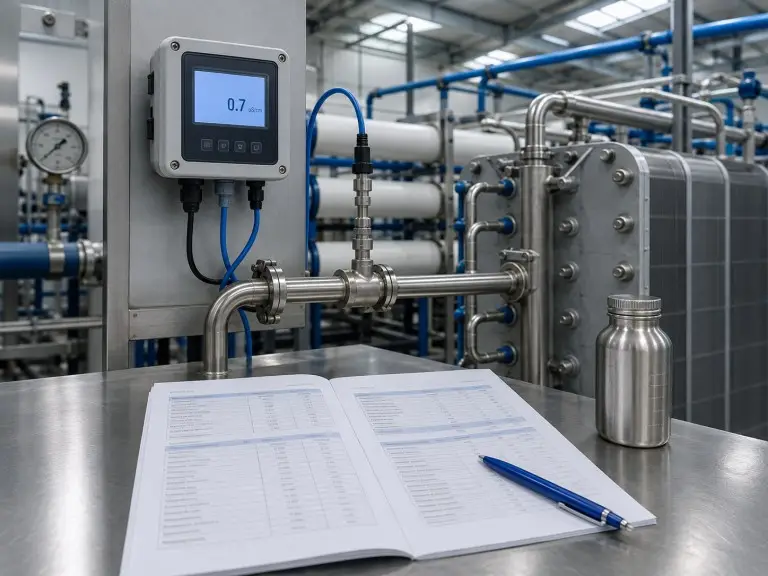
Feed Conductivity Equivalent (FCE) Screening. Standard conductivity does not fully represent the ionic load when CO2, silica, or boron are present in RO permeate. A common preliminary screening formula is:
FCE (µS/cm) ≈ measured conductivity + 2.79 × CO2 (ppm) + 1.94 × SiO2 (ppm)
For example, RO permeate measuring 8 µS/cm with 6 ppm dissolved CO2 and 0.3 ppm silica gives an FCE of approximately 25 µS/cm — above a typical 20 µS/cm EDI inlet limit even though measured conductivity alone looks acceptable. Coefficients vary between EDI module suppliers; final current configuration must follow the selected module manufacturer’s manual. If your water analysis lacks CO2 and silica data, we request these measurements before final sizing because conductivity-only sizing can undersize current capacity by 15–30% in pharmaceutical and semiconductor applications.
Source-water route boundary
If your source is brackish groundwater, we evaluate whether a single-pass RO stage can deliver permeate within EDI feed boundaries, or whether double-pass RO is needed upstream. For elevated salinity sources, review the brackish water reverse osmosis page. If the source is seawater, single-pass seawater RO permeate usually exceeds standard EDI feed limits; the seawater desalination system route must be reviewed first.
EDI vs. Mixed-Bed IX vs. Double-Pass RO
Buyers evaluating EDI often compare three polishing options: EDI, double-pass RO, and conventional mixed-bed ion exchange. The correct choice depends on feed-water chemistry, purity target, capital budget, and operating profile.
| Factor | EDI | Mixed-Bed IX |
|---|---|---|
| Regeneration | Continuous electrical regeneration with DC current. | Batch chemical regeneration with acid and caustic. |
| Operating mode | Continuous, no shutdown for regeneration. | Periodic shutdown for regeneration cycles. |
| Chemical use | No operating acid or caustic regeneration chemicals. | Regular chemical consumption and waste handling. |
| Chemical waste generation | No acid or caustic waste stream from regeneration. | Regeneration creates chemical waste that must be neutralized and handled. |
| Output stability | Stable product quality — typically < 0.1 µS/cm conductivity — when feed boundaries are controlled. | Quality varies as resin exhausts before regeneration. |
| Operating complexity | Lower daily chemical handling burden, but feed-water control must be strict. | Higher chemical storage, safety protocol, and regeneration scheduling burden. |
| Fit condition | Continuous ultrapure water and chemical-free operation. | Retrofit situations where batch regeneration infrastructure exists. |
| Factor | EDI | Double-Pass RO |
|---|---|---|
| Purity role | Final ultrapure polishing after RO. | Second membrane rejection stage for high-purity water. |
| Product quality | Design-dependent ultrapure range, commonly 5–18 MΩ·cm resistivity for pharmaceutical and semiconductor targets. | High purity, typically not final ultrapure by itself. |
| Weakly ionized species | Handled with correct FCE-based design. | Reduced but often not enough for final ultrapure targets. |
| Capital cost | Higher upfront polishing stage. | Lower upfront than EDI in many high-purity applications. |
| Energy profile | Low DC electrical input for regeneration. | Second high-pressure pump and second membrane array. |
| Long-term consumables | Ion exchange media has long service life when feed limits are maintained. | Second-pass membranes require replacement and periodic cleaning. |
| Output consistency | Continuous and stable when feed conductivity, FCE, and flow are controlled. | Continuous, but product quality changes with membrane age and feed quality. |
| Best fit | Pharma, semiconductor, boiler feed, continuous ultrapure use. | Moderate high-purity targets or upstream conditioning before EDI. |
When We Recommend EDI
EDI fits when the project needs continuous polishing above 10 MΩ·cm — pharmaceutical USP water, semiconductor rinsing, or high-pressure boiler makeup — and chemical-free operation is a process or compliance requirement.
When We Recommend Double-Pass RO First
Double-pass RO is the first step when single-pass permeate exceeds 20 µS/cm, when brackish or seawater source TDS drives residual ionic load above EDI capacity, or when the purity target is 1–10 µS/cm without needing final ultrapure resistivity.
If you are not certain which route fits, send us your source water analysis and target output specification through our quote request form. We review both options before committing to a configuration.
Our RO+EDI Water Treatment Train
The exact configuration depends on source water quality, target product water specification, and system capacity. We supply EDI as a standalone polishing stage or as part of a fully integrated RO+EDI skid.
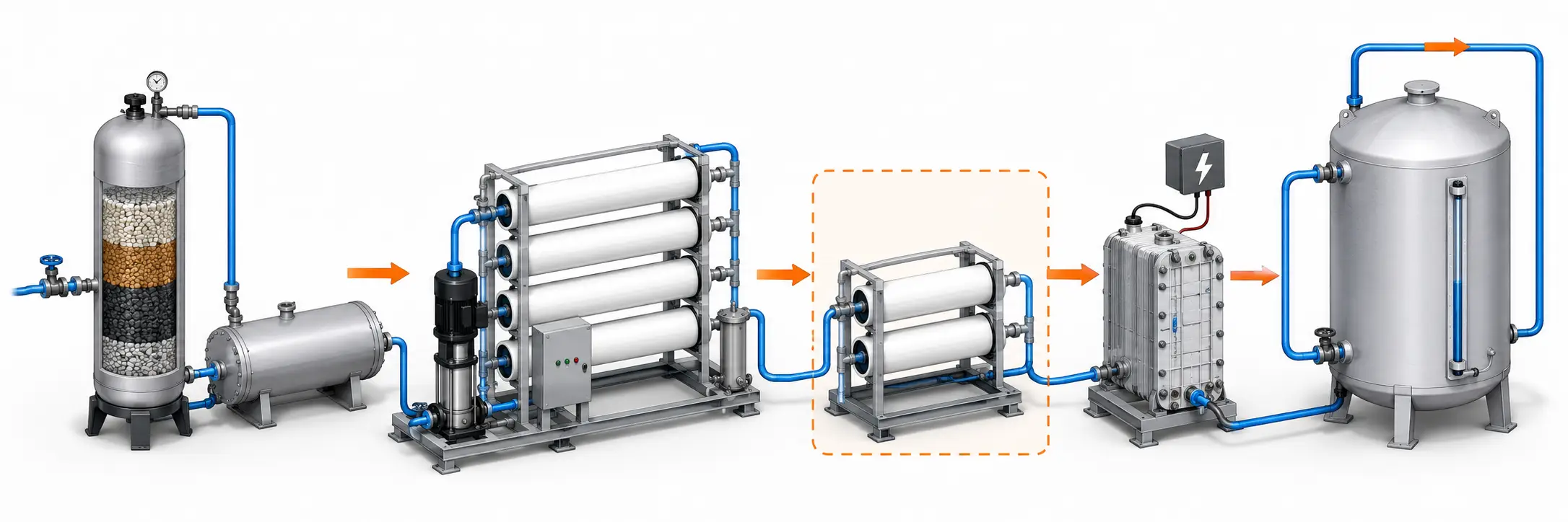
Pre-treatment
Source water first passes through the pretreatment train. Depending on the analysis, we specify sediment filtration, activated carbon filtration for dechlorination, antiscalant dosing, softening, and cartridge filtration. Pretreatment protects both the RO membranes and the downstream EDI unit; we do not treat it as a separate accessory.
Single-Pass RO
The primary RO stage removes most dissolved solids and produces the permeate that becomes EDI feed. For stable municipal supply, the upstream route may begin with a commercial RO water filter system. For wells, boreholes, or inland saline sources, we first review the brackish water reverse osmosis route.
Optional Double-Pass RO
A second RO pass is added when single-pass permeate conductivity exceeds EDI feed limits or when source-water salinity creates too much residual ionic load. We also review this stage when the target involves semiconductor or pharmaceutical polishing and the EDI inlet specification is narrow.
EDI Polishing Unit
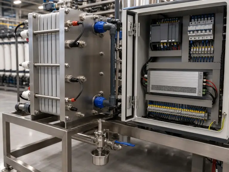
The EDI module stack receives RO permeate and drives residual ions through ion-selective membranes using DC electrical current. The ion exchange media inside the module is regenerated continuously by the same current, so no acid or caustic regeneration cycle is required during normal operation.
Product Water Distribution
Ultrapure product water flows to pharmaceutical production lines, semiconductor rinse systems, high-pressure boiler feedwater headers, laboratory supply, or process loops. Distribution hygiene, storage design, and point-of-use requirements are confirmed with the buyer before final configuration.
Integrated skid option. Integrated skids are pre-piped, pre-wired, and factory-tested before shipment. Full-skid assembly includes hydrostatic pressure testing, electrical continuity check, and PLC sequence verification before export crating.
System Configuration and Component Options
EDI systems are configured to match target flow rate, product-water specification, footprint, integration scope, and control architecture. Each specification is an engineering decision, not a catalogue selection.
Module Stack Configuration
EDI module stacks are the core ion removal element. Single-stack systems cover approximately 0.25–5 m³/h; multi-stack parallel or series configurations extend capacity to 50 m³/h and above. Standard skid materials include SS304 frame with SS316L wetted parts; FRP or UPVC piping is specified for high-purity applications. Power supply is configured to site voltage (220 V / 380 V / 415 V, 50 or 60 Hz).
Skid Integration Options
- EDI-only polishing skid for existing RO systems.
- Integrated RO+EDI skid for new installations.
- OEM/ODM configuration for system integrators, EPC contractors, and distributors.
Instrumentation and Control
Standard instrumentation includes inlet and product conductivity or resistivity transmitters, flow measurement, pressure gauges, and DC power monitoring. Control options range from manual start/stop with local alarm to full PLC with HMI touchscreen, SCADA signal output, and remote monitoring — selected based on project scale and integration requirements.
Applications by Industry
EDI applications differ by output quality, feed-water stability, hygiene requirements, operating continuity, and downstream process risk. The same EDI module is not specified identically for every industry.
Pharmaceutical Purified Water and WFI Feed Preparation
Pharmaceutical production facilities require water meeting USP conductivity and TOC limits — typically < 1.3 µS/cm and < 500 ppb TOC for Purified Water. EDI operating after properly designed RO pretreatment supports pharmaceutical-grade water generation while eliminating chemical regeneration, but final system compliance depends on the complete validated water system including storage, distribution, sanitization, microbial monitoring, and endotoxin control where applicable. Final compliance must be confirmed against the user’s process specification, validation protocol, and applicable pharmacopoeia.
Deionization water system solutionsSemiconductor and Electronics
Semiconductor and electronics manufacturing rely on an EDI water purification system for wafer rinsing, component cleaning, and process-water applications where ionic contamination below 1 ppb can affect yield. We review FCE, silica (target often < 5 ppb), CO2, and target resistivity (commonly ≥ 15 MΩ·cm) before sizing the EDI stage. Final compliance must be confirmed against the user’s process specification and applicable facility standard.
Power Generation
High-pressure boiler systems (≥ 60 bar) require feedwater with conductivity below 0.3 µS/cm and silica below 20 ppb to control corrosion, scaling, and steam-side carryover. Continuous EDI polishing after RO maintains stable boiler feedwater chemistry without regeneration interruptions.
Food and Beverage
Food and beverage manufacturers use high-purity process water — typically < 5 µS/cm conductivity — in rinsing, formulation, CIP make-up, and ingredient-water applications where mineral content affects product taste and stability. EDI’s chemical-free operation suits hygiene-focused environments that restrict chemical handling near production lines.
Bottled water plants and beverage water treatmentLaboratory and Research
Laboratory systems need consistent Type II or Type I water (≥ 1 MΩ·cm to ≥ 10 MΩ·cm) for analytical chemistry, reagent preparation, HPLC feed, and quality testing. EDI polishing units are available as standalone modules or as part of integrated laboratory water treatment trains.
EDI Operating Parameters and Design Targets
All values below are project-review parameters. Final specifications are confirmed during engineering review based on your feed-water analysis, target product water quality, application requirements, and system configuration.
| Parameter | Typical Range / Condition | Notes |
|---|---|---|
| Feed conductivity | ≤ 20 µS/cm; ideal ≤ 10 µS/cm | Higher conductivity requires additional upstream RO review. |
| Feed TDS | 1–20 ppm as RO permeate | Feed source and RO recovery dependent. |
| Hardness | < 1 ppm as CaCO3 preferred | Scaling risk inside EDI media. |
| Free chlorine | Zero at EDI inlet | Oxidants must be removed before EDI. |
| Feed temperature | 5–45 °C | Affects membrane and resin performance. |
| FCE | Typically 1.2–3× measured conductivity when CO2 > 5 ppm or silica > 0.5 ppm | Accounts for CO2, silica, and boron. |
| Product resistivity | Up to 15–18 MΩ·cm, design dependent | Application target, not a fixed guarantee. |
| Product conductivity | Generally < 0.1 µS/cm, project dependent | Confirmed from feed chemistry and design. |
| Silica target | < 20 ppb semiconductor; < 100 ppb pharma (project dependent) | Critical for semiconductor and pharmaceutical review. |
| System flow | 0.5–100 m³/h typical EDI range; provide peak and average demand | Provide m³/h or m³/day and peak demand. |
| EDI recovery | 90–95% typical; concentrate blowdown 5–10% of feed | Concentrate blowdown varies with feed and configuration. |
| Skid configuration | Single-stack, multi-stack, integrated RO+EDI | Capacity and integration requirements determine choice. |
The values above are Hiju preliminary design targets for EDI projects. Final limits depend on membrane model, feed-water analysis, recovery target, temperature, scaling projection, and pretreatment design.
Engineering Boundary Checks for EDI Sizing
When we review electrodeionization technology inquiries, we regularly find the same underspecified or incorrectly scoped requests. These notes help buyers prepare complete data and avoid rework during engineering review.
Conductivity Data Without CO2 or Silica. Feed conductivity alone is insufficient when dissolved CO2 or reactive silica is present. We calculate FCE to correct for weakly ionized species and request missing CO2 or silica measurements before final sizing. Conductivity-only sizing can undersize current capacity by 15–30% in pharmaceutical and semiconductor applications.
EDI Without RO Pretreatment. We receive inquiries for EDI systems treating softened water or process water directly. EDI feed must be RO permeate with conductivity ≤ 20 µS/cm. If the upstream RO stage is missing, we scope it as part of the full system rather than quoting an EDI module alone.
EDI directly after single-pass seawater RO+
Missing hardness data+
Fixed resistivity target without feed-water context+
What We Need to Size Your EDI System
An accurate electrodeionization system proposal requires project inputs that describe feed water, target output, operating profile, and site conditions. Complete data reduces review cycles and improves quotation accuracy.
Feed Water and Source
- Source water type and upstream RO route.
- TDS, conductivity, hardness, chlorine, CO2, silica, pH, iron, and contaminants.
- Existing RO configuration and current permeate conductivity.
- Feed water temperature range.
Target Output Specification
- Required product conductivity or resistivity.
- Silica limit for semiconductor or pharmaceutical use.
- TOC requirement if applicable.
- Application: pharma, semiconductor, boiler, food and beverage, laboratory, or other.
Capacity and Operating Profile
- Product water flow rate in m³/h or m³/day.
- Operating hours per day and days per year.
- Acceptable maintenance downtime.
- Peak and average demand profile.
Project and Site Details
- Project country or region.
- Available power supply and phase.
- Available footprint for skid placement.
- EDI-only or integrated RO+EDI scope.
- Custom branding or integrator documentation requirement, if applicable.
- Preferred contact method: WhatsApp, Email, or online inquiry form.
Why Hiju
Qingdao Hiju Thermal Power Co., Ltd manufactures industrial water treatment systems and supports export projects where equipment configuration, documentation, voltage, packaging, and shipment requirements must be confirmed before production.
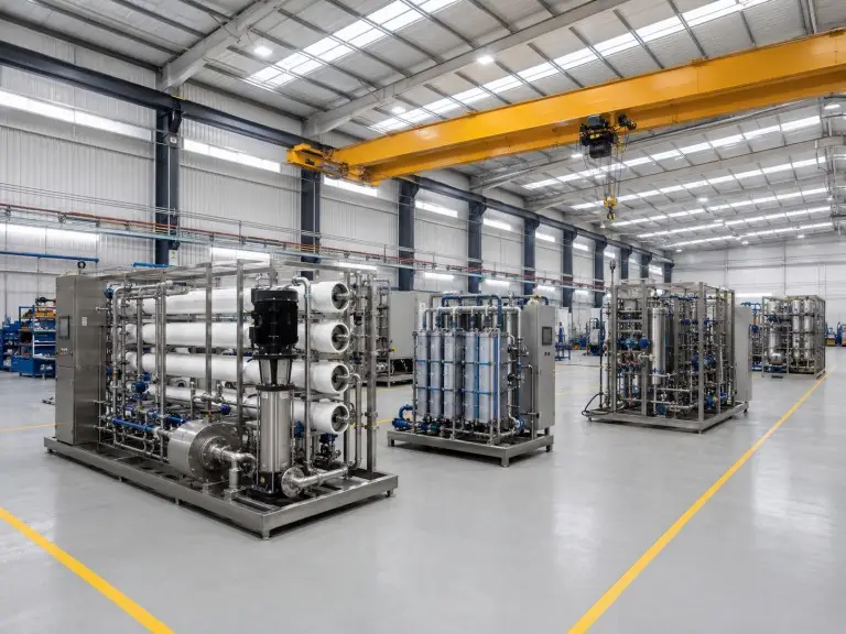
21,000 sqm workshop
Dedicated workshop for RO+EDI assembly, pressure testing, and final inspection.
Full-skid FAT
Factory acceptance testing before shipment.
50/60 Hz
Multi-voltage export configurations.
OEM / ODM
Custom branding and documentation.
Technical review note. This page was reviewed by Hiju’s water treatment engineering team. EDI sizing decisions are based on RO permeate conductivity, FCE calculation, CO2, silica, hardness, chlorine, flow rate, target resistivity, and application requirements. Final specifications are confirmed after reviewing the buyer’s water analysis and the selected EDI module supplier’s inlet limits.