Single Valve Double Tank Water Softener
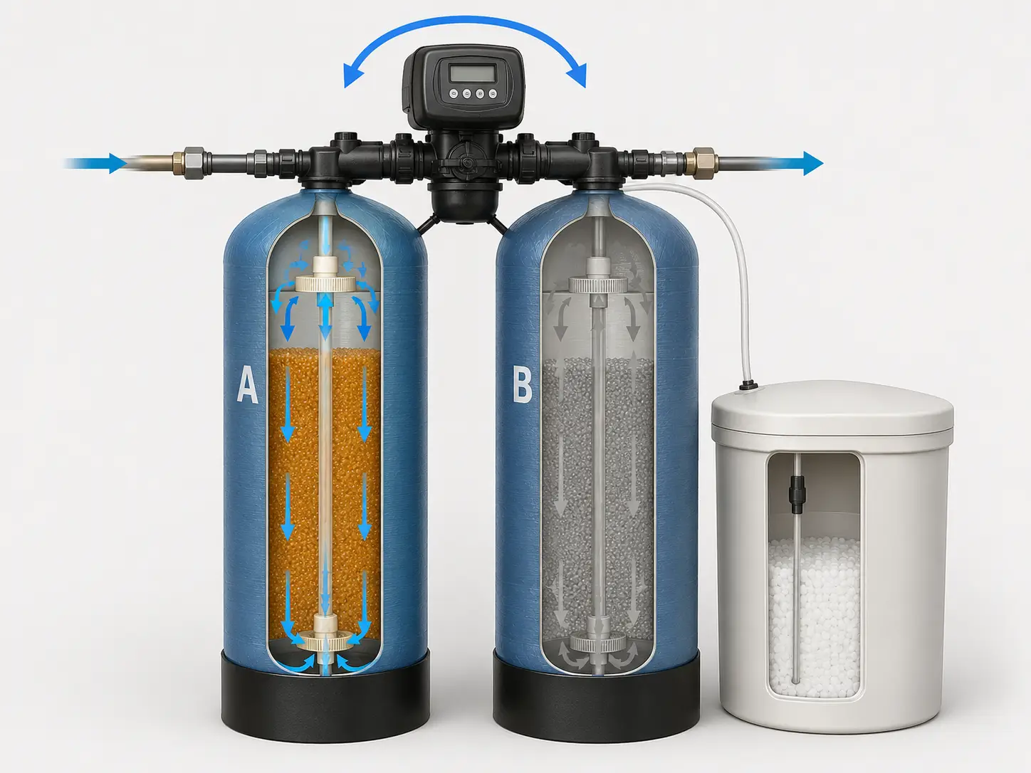
We use a single valve double tank water softener when the process requires continuous soft water and cannot schedule a regeneration window during production hours. Also known as a twin alternating softener or shared-valve duplex system, one shared control valve alternates service between two resin tanks so one tank delivers softened water while the other regenerates.
When the active tank reaches its metered trigger, the valve switches flow to the freshly regenerated standby tank before initiating regeneration on the exhausted bed. During normal programmed regeneration, soft water output is not interrupted.
One Shared Valve, Two Alternating Resin Beds
A single valve double tank softener delivers uninterrupted output by alternating service between two resin beds through one shared control valve. One bed is always in service while the other completes backwash, brine draw, slow rinse, and fast rinse.
Switchover completes without a supply gap
When the active tank’s metered trigger fires, the control valve redirects incoming feedwater to the standby tank in seconds, then regenerates the exhausted bed offline.
Cost and capability position
This configuration sits between single-valve single-tank and double-valve double-tank architectures. It delivers continuous service at lower mechanical complexity than two independent valves, but it does not provide full tank isolation during maintenance.
Three Conditions That Rule Out This Configuration
We identify these conditions before quoting because each one changes the mechanical architecture needed for reliable operation.
Maintenance Isolation Is Required
If either tank must be drained, inspected, or repaired without stopping supply, specify a double valve double tank water softener. A shared valve links both tanks operationally.
Planned Shutdown Windows Exist
If shift gaps or overnight shutdowns of 45–90 minutes or more align with regeneration, a single valve single tank water softener usually provides the lower-cost route.
Peak Flow Exceeds One Valve
If multiple supply lines or high peak demand exceed the capacity of one alternating valve assembly, a multi tank water softener provides the scalable route. We compare peak demand against the selected valve capacity at acceptable pressure drop before routing to multi-tank architecture.
Where This Configuration Sits in the Water Softener Line
Our water softener systems line covers four configurations. Operating hours, maintenance isolation, flow demand, and budget position determine the route.
| Configuration | When It Fits |
|---|---|
| Single valve single tank | Scheduled regeneration window available; intermittent or single-shift use |
| Single valve double tank | Continuous service required; no independent tank isolation needed; 24-hour or multi-shift demand |
| Double valve double tank | Full mechanical independence required; either tank must be isolatable without supply interruption |
| Multi-tank | High flow demand; parallel softening capacity across multiple supply lines |
How One Control Valve Manages Both Resin Tanks
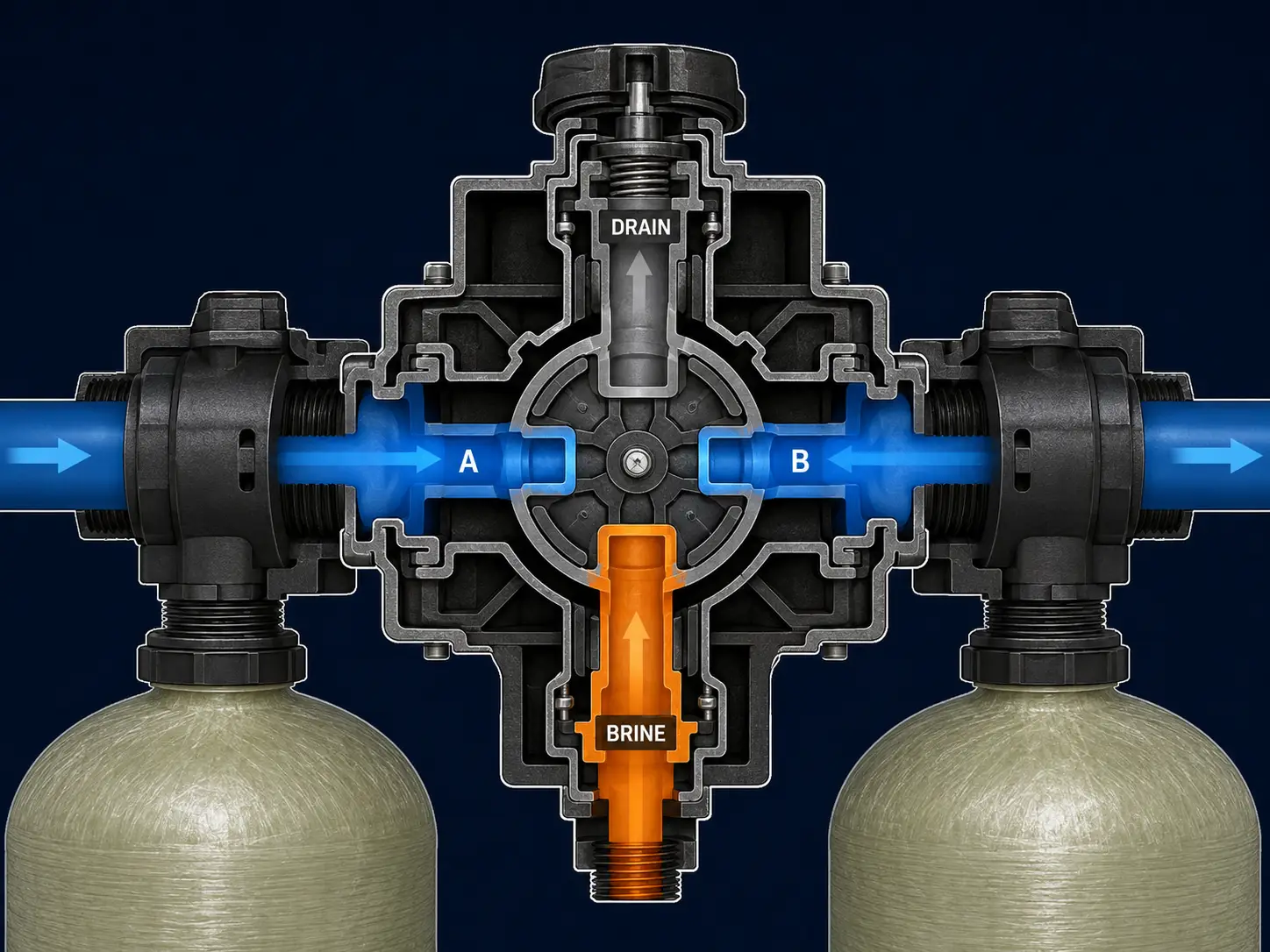
One multi-port control valve manages service, switchover, and regeneration across both resin tanks, keeping one bed in service while the other completes its four-stage regeneration cycle.
Backwash
Water flows upward through the exhausted resin bed to loosen compaction and flush accumulated suspended particles to drain.
Brine Draw
Concentrated NaCl brine enters the bed. Sodium ions displace accumulated calcium and magnesium from exchange sites.
Slow Rinse
A low-flow flush displaces residual brine at a rate that allows ion redistribution without disturbing bed structure.
Fast Rinse
A high-flow rinse removes remaining brine residue and restores outlet quality before the tank returns to standby.
Trigger mode
Volume-based triggering initiates regeneration when the active tank has processed a calculated volume from inlet hardness and resin capacity. We recommend this mode for most industrial applications because it responds to actual consumption.
Brine system
The brine tank holds saturated NaCl solution and is sized by expected regeneration frequency and maintenance interval for salt replenishment.
Service, Switchover, and Standby Tank Regeneration
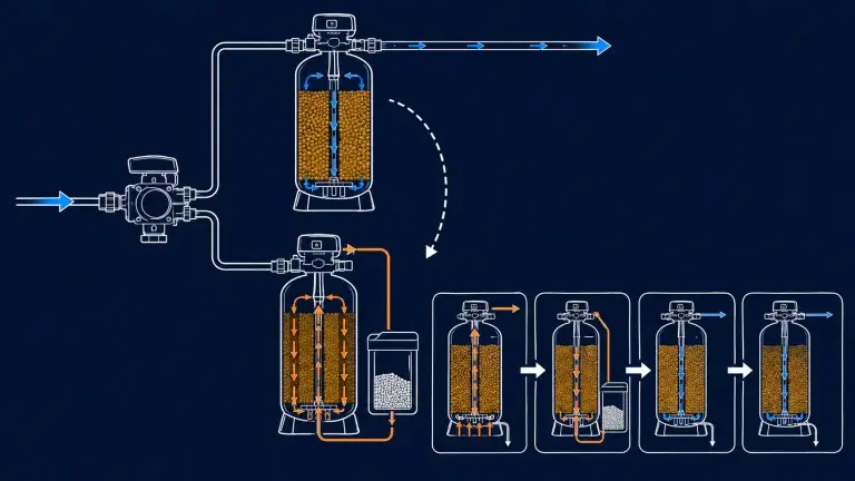
The process path runs from raw water inlet through the active resin tank to soft water outlet, while the standby tank completes regeneration in parallel.
Primary flow
Raw Water Inlet → Pre-filter if required → Active Resin Tank in service mode → Soft Water Outlet.
Parallel regeneration
Standby Tank → Backwash → Brine Draw → Slow Rinse → Fast Rinse → Standby ready for service.
Pre-filtration boundary
Pre-filtration is recommended when source water contains suspended solids above resin tolerance, or when iron and manganese can foul cation resin and reduce exchange performance; silica is checked mainly for downstream RO or boiler scaling risk. We confirm type and sizing from the water analysis.
Project Review Parameters for Alternating Duplex Softening
Sizing this system requires confirmed data across hardness, flow, peak demand, operating hours, water chemistry, and destination power supply. Without complete data, resin volume and trigger settings cannot be accurately determined.
| Variable | Typical Range | Notes |
|---|---|---|
| Inlet water hardness | Project-specific | Must be supplied from water analysis |
| Design flow rate | m³/h confirmed per project | Primary sizing input |
| Peak demand flow | m³/h highest instantaneous draw | Affects tank and valve sizing |
| Daily operating hours | Continuous 24h / shift-based / intermittent | Determines service volume between regenerations |
| Operating pressure | 0.2–0.6 MPa typical | Verify at softener inlet. Higher pressure or special tank material requirements reviewed by vessel and valve rating |
| Operating temperature | 5–40°C typical | Confirm installation environment |
| Outlet hardness target | Buyer-specified mg/L as CaCO₃ | Confirmed during review |
| Iron / manganese / silica | mg/L when present | Required for groundwater or industrial sources |
| Resin tank count | 2 fixed | Mechanical identifier of this configuration |
| Control valve count | 1 shared alternating valve | Defines the configuration boundary |
| Regeneration mode | Volume-based or timer-based | Metered preferred for industrial applications |
| Connection size | DN or inch per project piping | Confirmed in engineering |
| Tank material | FRP or steel with internal lining | Confirmed per project |
| Power supply | Voltage / frequency / phase | Variable by destination country. Valve motor voltage and control-panel supply may differ; confirmed by selected valve brand and destination requirements |
Application Scenarios for Single-Valve Double-Tank Softeners
Each application below needs uninterrupted soft water but does not require full independent tank isolation during maintenance.
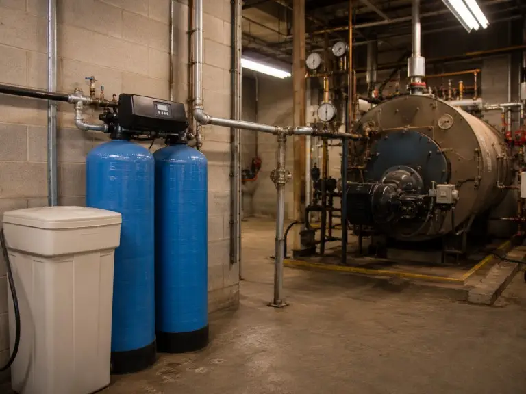
Boiler Feed Makeup
Continuous boiler operation requires soft water for the full operating schedule. In boiler feed water treatment, inlet hardness and daily operating hours drive tank sizing.
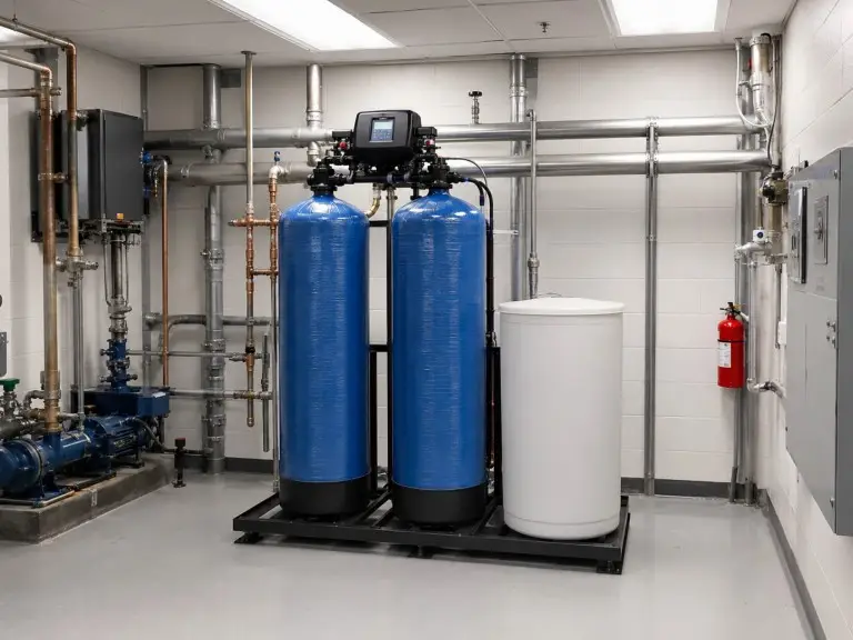
Hotels and Large Buildings
Peak morning and evening demand, not average use, drives the review for water filtration systems for commercial use projects.
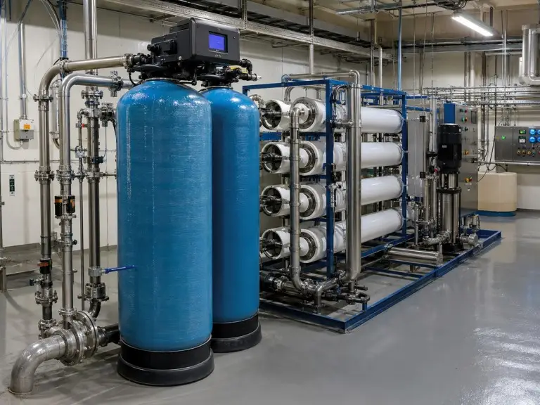
RO System Pretreatment
RO membranes require stable hardness control when the downstream RO runs continuously. We confirm hardness target, RO operating pressure, silica, and iron before specification.
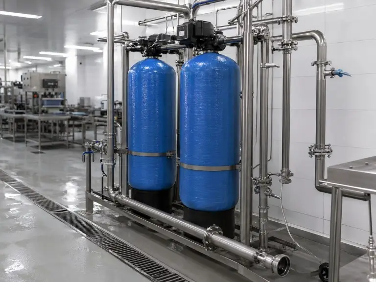
Industrial Process Water
Food production, electronics, and pharmaceutical process lines require consistent outlet hardness through regeneration transitions. We evaluate inlet variation and process quality tolerance before confirming fit. Final compliance must be confirmed against the user’s process specification, validation protocol, and applicable local standard.
Common Mistakes in Twin-Tank Softener RFQs
These errors consistently appear in project data and can produce undersized systems or configuration mismatches after installation.
Dual Tank Without Valve Count
Dual tank can mean one shared valve or two independent valves. We confirm valve architecture because it determines maintenance isolation and operational independence.
Average Flow Instead of Peak Flow
Using average daily consumption instead of peak hourly demand risks hardness breakthrough at peak draw. We require both values before tank sizing.
Omitted Iron, Manganese, or Silica
Elevated iron and manganese concentrations foul cation resin and are not reversed by standard NaCl regeneration. Silica is checked primarily for downstream scaling risk in RO or boiler applications. Water analysis controls the pre-treatment decision.
Fixed Outlet Hardness Guarantee
Outlet hardness depends on inlet composition, flow, resin volume, salt purity, and trigger settings. We size to the buyer’s target after review.
Default Regeneration Frequency
Too-frequent regeneration wastes salt and water; too-infrequent regeneration causes hardness breakthrough. Trigger settings are commissioned from real operating data.
Sizing Inputs for This System
A full water analysis at initial contact is the fastest path to a complete quotation. Partial data produces provisional sizing and a second review round.
| Input | Notes |
|---|---|
| Raw water hardness | mg/L CaCO₃ or mmol/L from water analysis |
| Design flow rate | m³/h operational process requirement |
| Peak demand flow | Highest instantaneous draw in the operating schedule |
| Daily operating hours | Continuous 24h, multi-shift, or intermittent |
| Outlet hardness target | mg/L CaCO₃ process specification |
| Operating pressure and temperature | Measured at the softener inlet |
| Iron, manganese, silica, TDS | Required when the source is groundwater or industrial supply |
| Power supply and connection size | Voltage, frequency, phase, DN or inch piping |
| Destination and project type | Certification, voltage, and documentation path |
| OEM/ODM requirement | Valve brand, tank material, labeling, documentation |
Why Hiju Handles Alternating Softener Projects
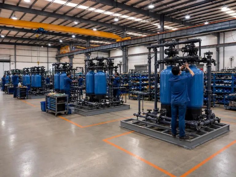
We manufacture and export water treatment equipment from a 70,500 sqm production facility with 21,000 sqm of workshop space, supported by 78 technicians and 28 engineers. Our equipment range carries CE and ISO 9001 certification. ASME-coded vessel documentation is available on request for procurement environments that review multiple standards.
Since 2016, we have supplied buyers in Southeast Asia, the Middle East, Africa, South America, and Central Asia. OEM and ODM configurations are available when a buyer requires valve brand preferences, tank material options, or private-label production.