
Industrial Salt Tanks and Brine Tanks for Water Softener Systems
Brine tanks are the active regeneration component at the heart of every ion exchange water softener system. We manufacture and supply PE brine tanks — 25 L to 2,000 L standard range — as part of complete softener systems or as standalone replacement components for existing installations. Our full range of water storage tanks supply — including stainless steel water tanks, PE plastic water tanks, and FRP water tanks for passive storage — is available from the category hub if your application calls for something different.
How Brine Tanks Drive Ion Exchange Regeneration
A brine tank participates actively in three of five regeneration phases. An incorrectly sized or poorly maintained tank causes the entire softener to fail silently — hardness breaks through without triggering any alarm.
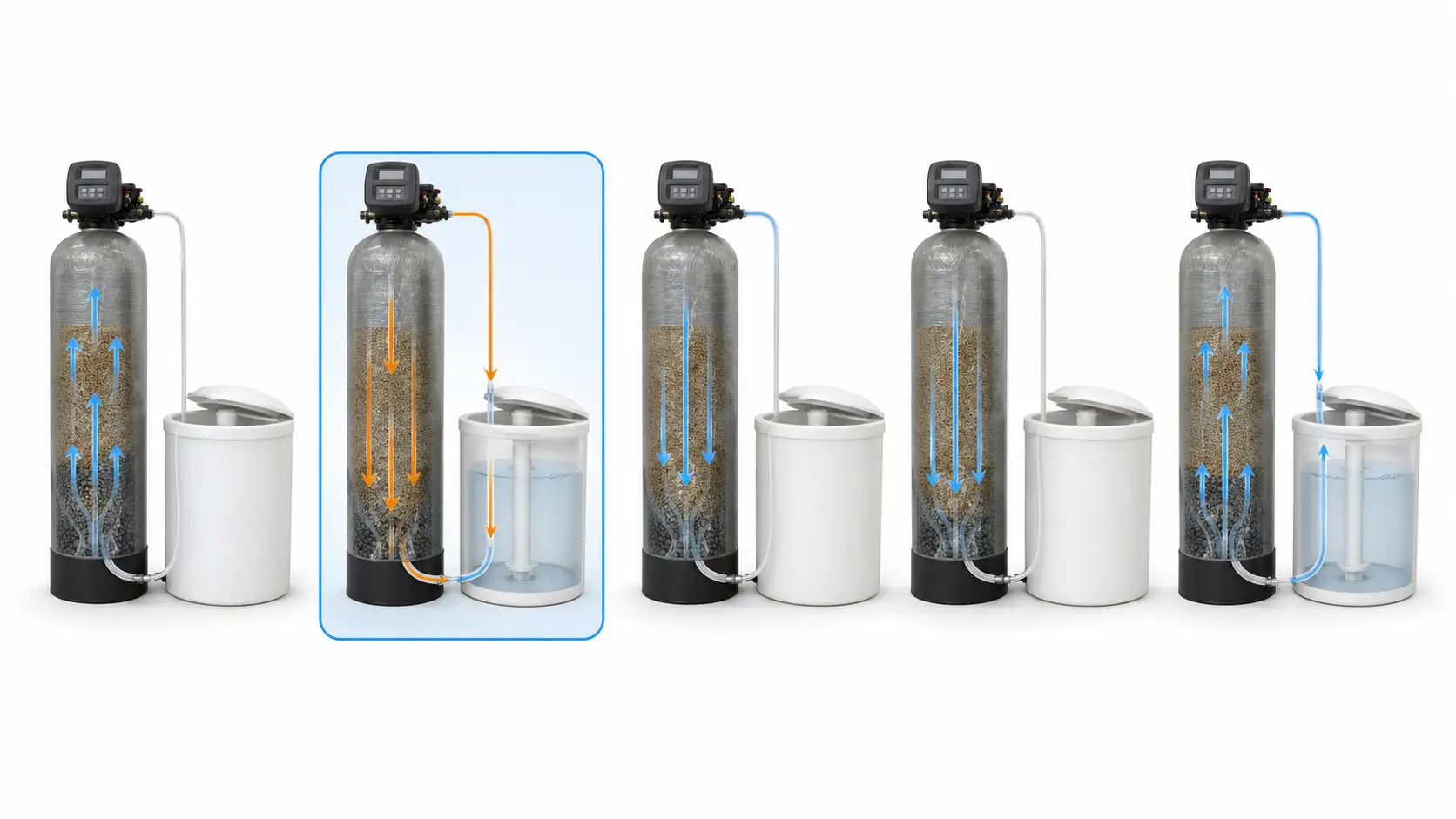
Backwash
Flow reverses through the resin vessel to loosen and flush accumulated suspended solids. The brine tank is idle — no brine is drawn in this phase.
Brine Draw
Saturated NaCl solution (~26.4% at 15–20°C) is drawn from the brine tank through the brine line into the resin vessel. Sodium ions displace calcium and magnesium from the resin. If the tank runs dry mid-phase, regeneration is incomplete and hardness breaks through.
Slow Rinse (Brine Push)
Fresh water slowly displaces hardness ions and residual brine to drain. The brine tank is idle.
Fast Rinse
High-flow rinse clears residual brine and displaced hardness ions from the resin bed. Treated water quality is confirmed before the system returns to service.
Brine Refill
A calculated volume of fresh water returns to the brine tank to dissolve the next salt charge. Brine saturation takes 2–8 hours — duplex systems allow one vessel to stay in service while the other regenerates.
A tank holding only 1–2× the per-cycle salt charge will exhaust working salt between service intervals. Once salt drops below the brine well intake, the draw phase pulls dilute water — resin is incompletely regenerated and residual hardness passes through into the supply. Scale accumulates on boiler heat-transfer surfaces and RO membrane feed spacers: expensive to reverse, routinely misattributed to equipment failure rather than its actual cause.
Standard PE Brine Tank Specifications: 25 L to 2,000 L
The table below covers our standard PE brine tank range. All tanks operate at atmospheric, non-pressurized conditions. Capacity figures above 2,000 L and non-standard configurations are available via project review.
| Capacity (L) | Salt Capacity (kg, approx.) | Shape | OD x H (mm) | Brine Well ID (mm) | Connection | Material | Colors |
|---|---|---|---|---|---|---|---|
| 25 | ~10 | Square barrel | 225 x 225 x 460 | —† | 3/8″ OD | PE | Blue, White |
| 60 | ~25 | Square barrel | 330 x 330 x 600 | 90 | 3/8″-1/2″ OD | PE | Blue, White |
| 100 | ~40 | Round conical | Dia. 450 x 780 | 90 | 1/2″ OD | PE | Blue, White, Black |
| 250 | ~100 | Round conical | Dia. 630 x 1,050 | 100 | 1/2″ OD | PE | Blue, White, Black |
| 500 | ~200 | Round conical | Dia. 850 x 1,200 | 110 | 1/2″-3/4″ OD | PE | Blue, Black |
| 1,000 | ~400 | Round conical | Dia. 1,100 x 1,480 | 135 | 3/4″ OD | PE | Blue, Black |
| 2,000 | ~800 | Round conical | Dia. 1,360 x 1,690 | 135 | 3/4″-1″ OD | PE | Blue, Black |
† The 25 L square barrel unit does not include a standard brine well assembly; brine line pickup is via tank floor fitting. Brine well internal diameter applies from 60 L and above.
Salt capacity figures are approximate and assume dry-weight NaCl pellets loaded to normal working level. Exact working salt capacity depends on tank geometry and brine well clearance. Dimensional data above is for reference; confirmed drawings are issued during project review. Custom dimensions, brine well diameters, and connection sizes are available on request.
Configuration Options, Standard Components, and Custom Assembly
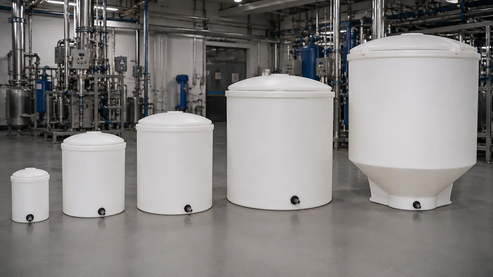
Our salt tanks and brine tanks are available in round and square configurations. Square barrel tanks (25–140 L) suit tight rectangular footprints; round conical tanks (60–2,000 L) are standard for larger installations — the conical base consolidates salt fines toward the brine well pickup, reducing mushing.
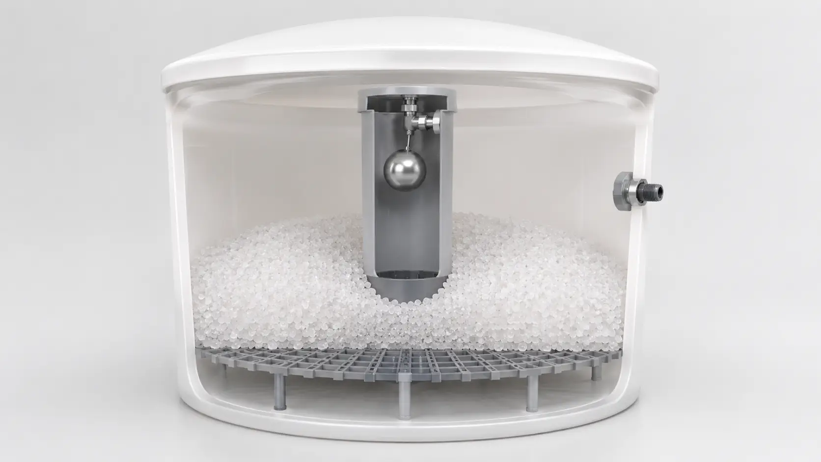
Brine Well (Riser Tube)
Internal riser through which saturated brine is drawn by the control valve. Internal diameter must match the control valve pickup tube. Mismatch causes restricted draw rate or air ingestion — we confirm this dimension against your valve specification.
Safety Float Valve
Prevents tank overflow if the control valve refill phase fails to shut off. Without it, a malfunctioning valve will overflow the tank indefinitely.
Overflow Fitting
Secondary drain path at tank wall level routing excess water to drain before it floods the equipment room floor.
Salt Grid / Support Grate
Injection-molded platform holding the salt charge above the water level. Grid clearance above the tank base is the primary design defense against salt paste accumulating at the brine well intake.
Lid
Standard sealed lid for indoor installations. Large-lid or open-top available for high-volume manual salt loading. UV-stabilized black PE required for outdoor sun-exposed installations.
Custom-configured supply is available — non-standard dimensions, brine well diameters, connection sizes, colour, and labeling are confirmed at project review.
Sizing the Brine Tank Correctly: The 6× Salt Charge Rule
The most common error is selecting a brine tank based on resin vessel volume alone. This produces undersized tanks in almost every case.
Working salt capacity ≥ 6× salt consumed per single regeneration cycle — absorbs refill interval variation and provides a visible reserve warning.
More resin = more brine required to fully regenerate loaded exchange sites.
Higher hardness loads more Ca²⁺/Mg²⁺ per service cycle, requiring more salt to displace.
Higher throughput exhausts resin faster and increases regeneration frequency.
Regeneration Level
Economy regeneration uses less salt per cycle but achieves lower resin restoration. Standard or thorough regeneration is required where consistent near-zero hardness is the output target. Economy level is appropriate only where treated-water quality targets are modest.
A residential-scale 18″ × 33″ brine tank submitted against an industrial duplex system handling 800 m³/day will exhaust salt between regeneration events and produce hardness breakthrough within 24–48 hours. We prevent this by sizing from the data — not from catalog defaults.
The 6× rule is an engineering sizing guideline, not an industry code requirement. Unmanned sites or 24/7 duplex systems may require 10–14 days of salt reserve. Final sizing confirmed per project.
Salt Bridge, Mushing, and Engineering Prevention
These two failure modes cause apparent softener malfunction that is actually a brine tank maintenance issue. Both are mechanical problems with known engineering solutions.
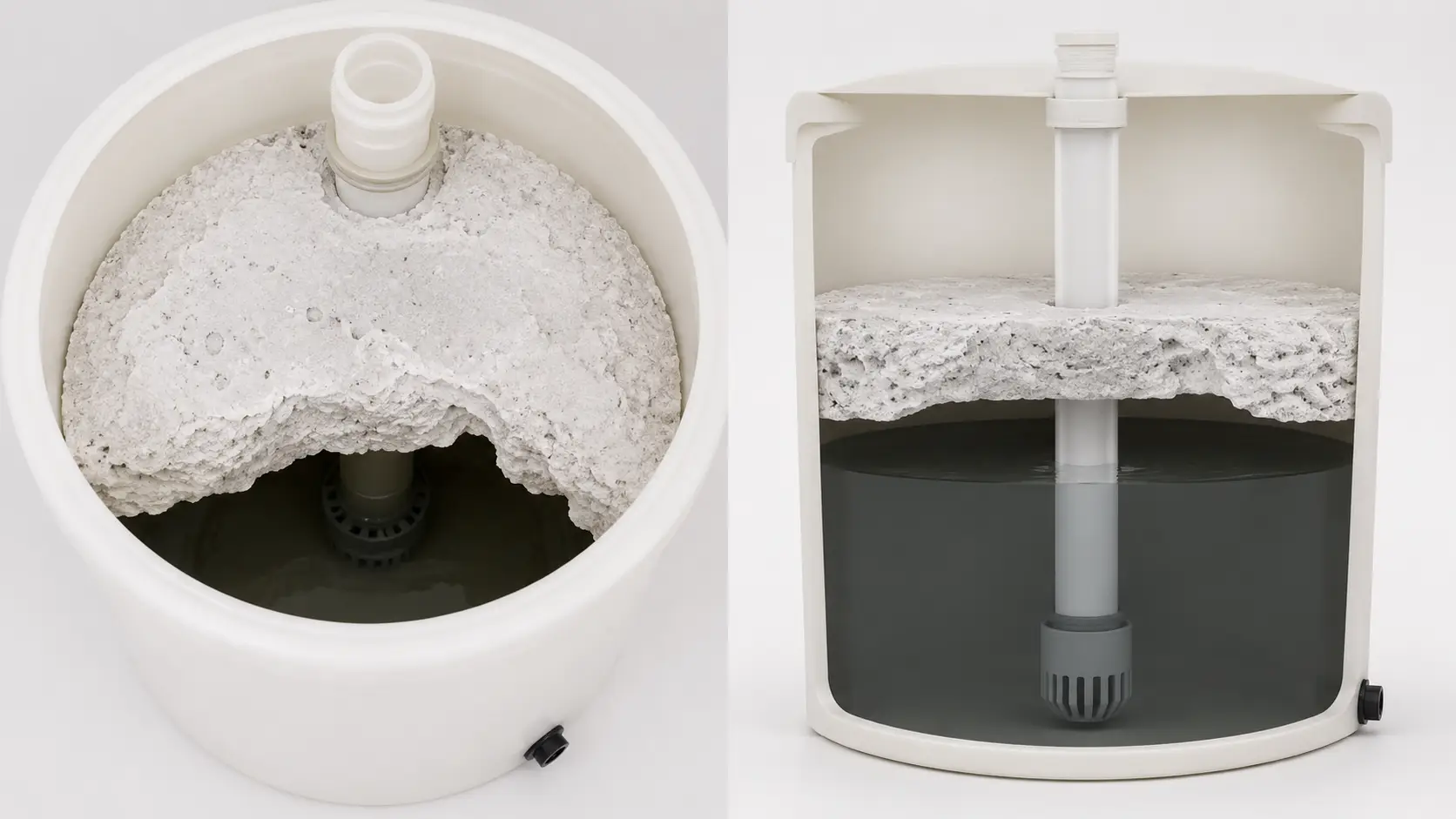
Salt Bridge
A hardened crust spans the tank interior above the water line. The tank appears full. Below the crust is an air gap — brine draw pulls near-zero-concentration water and regeneration completes with dilute brine. Resin is incompletely regenerated; hardness passes through without triggering any system alarm.
Prevention: Pellet-form salt · correct refill water level · salt grid geometry limiting wall contact area.
Mushing (Salt Paste)
Fine salt particles dissolve incompletely and settle as a semi-solid paste at the tank base around the brine well intake. Once the paste reaches the intake, brine draw flow is restricted — brine concentration becomes inconsistent and regeneration is partial. Often diagnosed as resin failure.
Prevention: Pellet salt · periodic brine well inspection · salt grid clearance designed to prevent paste reaching the intake.
Salt Tanks and Brine Tanks: Applications Across Industrial Sectors
Brine tanks appear in boiler rooms, hotels, food plants, healthcare facilities, and heavy industrial utilities. Each application changes the salt reserve, regeneration frequency, and control requirement, so the entries below include operating conditions rather than generic claims.
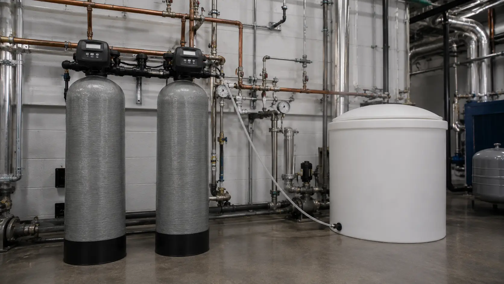
Boiler Feed Water Treatment — Continuous Demand, Zero Hardness Target
Boiler systems are the highest-consequence application for softener sizing and brine tank capacity. Residual hardness in boiler feed water initiates carbonate and silica scale formation on heat-transfer tube surfaces — the acceptable threshold depends on boiler pressure, feedwater standard, and downstream treatment design; many high-pressure boiler projects require near-zero hardness to prevent scale on heat-transfer surfaces. Even thin scale deposits measurably reduce thermal efficiency, increase fuel consumption, and create local hot spots that risk tube failure. Boiler plants at medium and large scale typically require duplex softener systems to ensure 24/7 soft water supply without service interruptions. We size the brine tank for duplex operation — sufficient salt capacity to supply two full regeneration cycles in sequence without manual refill. Our boiler feed water treatment solution page covers the complete system context.
Hotel and Commercial Building — Peak Flow and Scale Prevention
Hotel installations combine two distinct softening demands: laundry operations, which consume large volumes of hot water at near-continuous flow during morning linen cycles, and plumbing protection for heat exchangers, calorifiers, and copper distribution piping. Peak flow sizing must account for laundry machine banks operating simultaneously. We recommend metered regeneration control, triggered by volume throughput rather than a fixed time clock, because occupancy variation makes time-based regeneration inaccurate. Our water filtration systems for commercial use solution page covers system configuration for full-property installations.
Food and Beverage Processing — Sodium Control and KCl Option
Food plant process water softening introduces a selection variable absent from other industries: sodium content of the treated water. As a reference approximation from standard ion exchange chemistry, NaCl softening adds approximately 8 mg/L sodium per gpg of hardness removed — the exact figure depends on resin type, regeneration efficiency, and rinse volume, which we account for in the project specification. Where product formulation, regulatory limits, or process specifications restrict sodium input, we supply brine tanks configured for potassium chloride (KCl) regeneration. The process mechanics are identical; the brine tank, brine well, and connections are the same. Our bottled water plants solution page covers the wider pre-treatment scope.
Pharmaceutical and Healthcare — Pre-Treatment Upstream of WFI Systems
Upstream water softening is a standard step in pre-treatment trains feeding reverse osmosis systems that ultimately produce water for injection (WFI), purified water, or clean steam generation. Softening upstream of RO protects membranes from hardness scaling, extending cleaning intervals and membrane service life. In pharmaceutical contexts, the brine tank salt charge must use pharmaceutical- or food-grade NaCl to avoid introducing process contaminants during regeneration. We specify material grade during project review and confirm compatibility with your facility’s material qualification requirements. For food, beverage, healthcare, or pharmaceutical pre-treatment systems, specify salt grade and require COA, SDS, heavy metal limits, insoluble matter limits, and supplier traceability in addition to process specification compliance. Final compliance must be confirmed against the applicable process specification, validation protocol, and applicable local standard.
Industrial Manufacturing — High-Hardness Regions and Duplex Sizing
Manufacturing facilities in high-hardness regions — groundwater above 250–400 mg/L as CaCO₃ is reported across parts of the Middle East, South Asia, and Sub-Saharan Africa — require high-capacity softening to prevent rapid scale accumulation in cooling tower fill media, plate heat exchangers, and process vessel jackets. High-hardness influent means higher per-cycle salt consumption and more frequent regeneration, both of which drive brine tank sizing upward. For influent hardness above 400 mg/L, we typically recommend duplex systems with brine tanks sized for 10–14 days of salt reserve at the calculated regeneration frequency.
System Integration: Matching Valve, Resin Vessel, and Brine Line
Our salt tanks and brine tanks integrate with standard softener control valves, resin vessels, and brine line configurations. Each companion component must be matched to the tank specification for correct operation.
| Component | Match Requirement | Failure if Mismatched |
|---|---|---|
| Control Valve | Brine well internal diameter must match valve pickup tube — confirmed per valve platform (Fleck, Autotrol, Clack, equivalents) | Restricted brine draw rate or air ingestion; inconsistent brine concentration per cycle |
| Resin Vessel | Primary input for brine tank sizing — when we supply a complete system, brine tank and resin vessel are sized as a matched pair | Undersized brine tank → salt exhaustion between refills → hardness breakthrough |
| Brine Line + Check Valve | 3/8″–1/2″ OD tubing; check valve required to prevent backflow into tank during fast rinse phase | Without check valve: brine dilution and unnecessary safety float activation |
| Bypass Valve | Three-port bypass allows system isolation for maintenance without interrupting facility water supply | No bypass = full plant water interruption during every service event |
| Salt Level Sensor (optional) | Float-type or ultrasonic sensor connected to BMS or panel alert — recommended for unmanned or 24/7 sites | Without sensor: empty tank goes undetected until hardness breakthrough triggers a maintenance call |
For standalone replacement orders, provide the control valve model, existing brine tank dimensions, and brine line connection size — we confirm an exact-match replacement without requiring a full system resizing.
Manufacturing Since 2016 — ISO 9001 Quality System and Project Documentation
Qingdao, China · established 2016
PE tank production, assembly, QC
Production technicians + engineers
SE Asia · Middle East · Africa · S America · C Asia
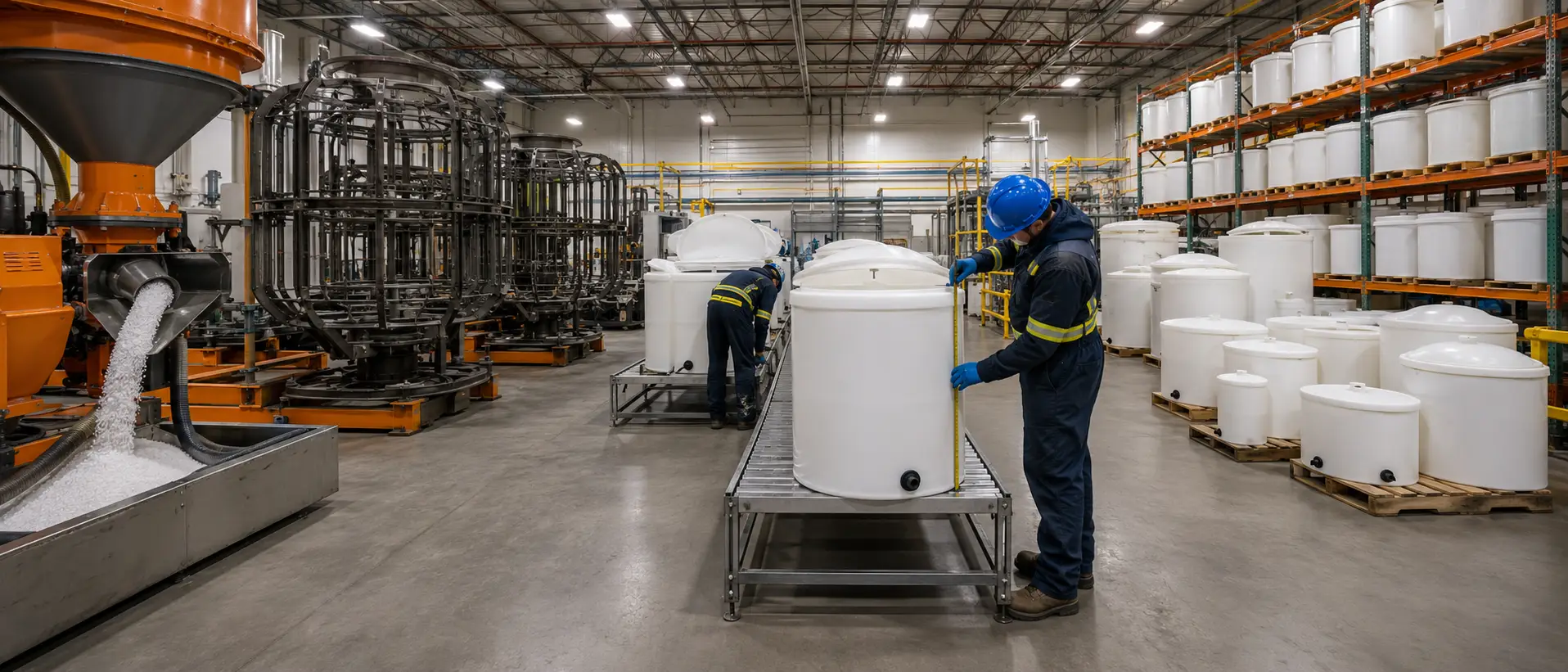
ISO 9001 + CE documentation
Manufactured under ISO 9001 quality management. CE documentation for applicable export packages. ASME-related documentation is available for pressure-vessel products within our range — not standard atmospheric PE brine tanks.
OEM / ODM workflow
Custom dimensions, brine well specifications, colour, and labeling are available for water treatment equipment assemblers and system integrators. All configurations proceed through engineering review before production.
Complete softener packages
For buyers sourcing a complete water softener system, we coordinate resin vessel, control valve, bypass valve, brine tank, and brine line as a commissioning-ready matched package from a single engineering review to delivery.
What Our Engineering Team Needs to Confirm Your Sizing
Send the following information to our engineering team and we will confirm brine tank sizing, component specification, and compatibility with your system or existing installation. For project quotations, the more inputs you provide, the more precise and final our specification will be on the first pass.
- Influent water hardness — mg/L as CaCO₃ or gpg; water analysis report preferred
- Daily or peak flow rate — m³/h or GPM; note if flow is continuous or intermittent
- Existing or planned resin vessel volume — liters or cubic feet
- Regeneration frequency — daily, every N days, or meter-initiated; state control valve model if meter-initiated
- Paired control valve model or brand — Fleck / Autotrol / Clack / other; model number if available
- Installation type — above-ground standard or below-ground pit; state pit dimensions
- Indoor or outdoor — UV exposure condition; state if direct sun
- Salt type preference — NaCl standard or KCl low-sodium for food, pharmaceutical, or low-sodium application
- System application and industry — boiler, hotel, food processing, pharmaceutical, industrial, municipal, other
- Downstream equipment — boiler, RO system, process equipment, heat exchanger
- Site space constraints — maximum tank diameter or height if applicable
- Destination country and port — for export documentation, certification requirements, and shipping configuration