
CIP Cleaning System for RO Membranes
Factory-assembled CIP membrane cleaning systems for in-situ chemical cleaning of RO, NF, UF, and MF membrane arrays without removing any element. CE documentation and ISO 9001 certification available; ASME qualification scope available on request for applicable pressure assemblies. OEM and export manufacturing available.
RO Membrane CIP Cleaning Triggers and Performance Thresholds
Your RO system does not fail suddenly. Performance declines in measurable steps, and three normalized metrics define when a CIP cleaning cycle should be initiated, not when the system has already been operating below design for months.
Normalized Permeate Flow Decrease — against 48-hour commissioning baseline, not nameplate design flow. A 10% drop from that baseline is the industry-consensus trigger. Waiting until losses reach 20-25% risks chemically irreversible fouling: the foulant has bonded structurally and no CIP cycle can fully restore rejection or flow.
Differential Pressure Increase — normalized against 48-hour commissioning baseline. A 15% DP increase signals that foulant resistance has become structural inside the feed channels. Operating past this point accelerates membrane compaction and risks physical damage to element seals and end caps.
Normalized Salt Passage Increase — against 48-hour commissioning baseline, per membrane manufacturer’s limit, commonly 5–10%. Salt passage increase is the more precise indicator used in membrane supplier technical manuals (e.g. DuPont FilmTec) for CIP trigger decisions in pharmaceutical, electronics, and boiler feedwater applications.
If your system is showing any one of these three indicators, a scheduled CIP cleaning cycle is the correct first response in the large majority of cases. We review current normalized performance data and feed water conditions before confirming system sizing, because the right CIP configuration depends on how far performance has declined and what fouling mechanism is driving it.
We design CIP skids for conditions where membrane fouling is chemically recoverable, and we identify cases where it is not during engineering review. Performance decline above 30% normalized flow accompanied by sustained high differential pressure frequently indicates fouling bonded beyond the reach of standard CIP chemistry; element inspection or replacement is then the correct next step. Systems with chronically inadequate pre-treatment, SDI consistently above 5, or iron and manganese not reduced upstream of the RO train, will re-foul within weeks of each cleaning cycle. Biopharmaceutical and certain pharmaceutical applications requiring cleaning temperatures above 80°C are managed as a specific configuration option, confirmed during materials selection review.
What Is a CIP Membrane Cleaning System?
A CIP system recirculates controlled chemical cleaning solution through your membrane array in-situ, without removing elements or disconnecting housings, at high flow rate and low differential pressure to dislodge and carry loosened foulants from the feed channels.
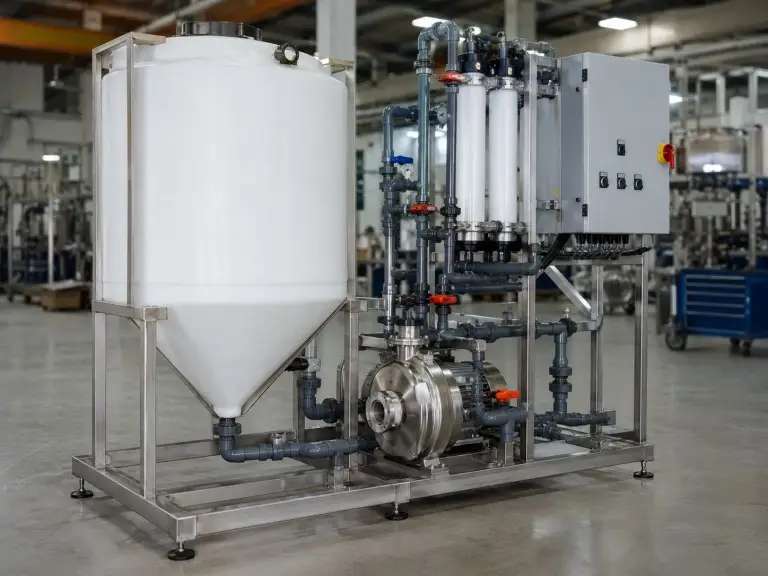
A Clean-In-Place (CIP) membrane cleaning system recirculates a controlled chemical solution through your membrane array without removing any element from its pressure vessel or disconnecting any housing from the train. The system prepares the cleaning solution at the correct concentration, filters it to 5–20 µm before it enters the circuit, and circulates it at high flow rate and low differential pressure to dislodge and carry loosened foulants from the feed channels.
Our CIP systems are compatible with RO, NF, UF, and MF membrane geometries, sized for standard 4-inch and 8-inch elements, and service 1–6 pressure vessels per cleaning circuit. The skid arrives factory-assembled and ready for site connection.
Skid-Mounted, Factory-Assembled
Pump, conical-bottom chemical tank, cartridge filter housing, instrumentation panel, and interconnecting piping are mounted on a structural frame and tested before shipment. Site work is limited to inlet/outlet connections and power supply.
Engineering Review Before Quotation
We check cleaning circuit volume, vessel count, connection location, return-line routing, chemical tank drainability, cartridge filter pressure drop, and site power as one operating loop — preventing the common field problems that appear after installation.
Export from Qingdao
As part of the water treatment parts range we manufacture and export, the CIP skid is the active process tool that restores membrane elements to their commissioned performance when fouling intervenes. OEM and export configurations available.
RO Membrane Cleaning Chemicals by Foulant Type
Not all fouling responds to the same chemistry. Selecting the wrong cleaning agent, or the wrong sequence, leaves foulants in place, or in the worst case, bonds them more firmly against the membrane surface. Our CIP membrane cleaning system review includes feed water analysis and fouling history before confirming the cleaning protocol.
| Foulant Class | Typical Feed Condition | Chemical Approach | pH Target | Cleaning Priority |
|---|---|---|---|---|
| Inorganic scale (CaCO3, CaSO4, silica) | Hard water, high TDS, high system recovery | Acid cleaning | pH 2–3 | Lead with acid only if scale is confirmed dominant and organic load is low. |
| Organic fouling (NOM, humic acids, dissolved oils) | Surface water source, treated effluent reuse | Alkaline cleaning (NaOH + surfactant) | pH 11–12 | Lead with alkaline when organic fouling is confirmed or suspected. |
| Biological fouling / biofilm | Warm feed water, low or interrupted chlorine residual | Alkaline + disinfection | pH 11–12 | Always lead with alkaline; confirm biofilm presence before specifying acid stage. |
| Colloidal / silt fouling | High SDI feed water, inadequate coagulation upstream | Alkaline dispersant | pH 11–12 | Lead with alkaline; review pre-treatment adequacy concurrently. |
Engineering judgment: alkaline before acid when both foulants are present. When feed water analysis indicates both organic or biological fouling and inorganic scale, which is common in surface water systems and industrial wastewater reuse, the alkaline stage must be run first. Acid applied to an organically fouled membrane in reverse osmosis surface partially dissolves the inorganic layer beneath while reducing cleaning effectiveness and fixing organic deposits more firmly on the membrane surface, making subsequent alkaline cleaning less effective. We design CIP cleaning sequences with this sequence logic as the default for any system where fouling history is ambiguous or mixed.
Cleaning pH, temperature, contact time, and chemical selection must follow the membrane manufacturer’s cleaning limits for the specific RO, NF, UF, or MF element installed. The values in this table are starting references for standard industrial RO/NF cleaning and are not universal limits for all membrane types.
Five-Stage CIP Cleaning Procedure for RO Membranes
A correctly executed Clean-In-Place (CIP) cycle runs in five distinct stages. Each stage performs a specific function; skipping or shortening any stage reduces cleaning effectiveness and causes problems in subsequent stages. The sequence below describes standard protocol for mixed or unknown fouling.
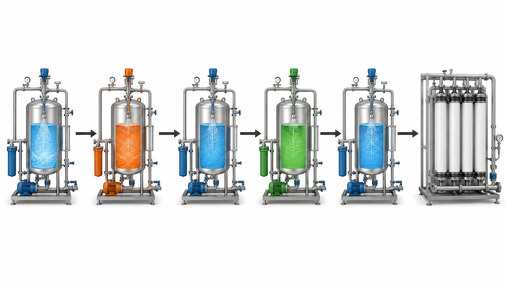
Pre-Rinse
Flush the membrane array with clean permeate or product water to displace feed water and bulk loose foulants from the flow channels before any chemical is introduced. Pre-rinse volume is typically one to two complete system volumes. Elevated backpressure during flushing can force displaced foulants into the active membrane layer rather than out of the system.
Alkaline Cleaning
Circulate alkaline cleaning solution at pH 11–12, at a solution temperature not exceeding 45°C, for 30–60 minutes. This stage targets organic fouling, biofilm, and colloidal deposits. High cross-flow velocity mechanically carries loosened foulants out of the feed channels; high pressure alone does not achieve this effect.
Intermediate Rinse
Flush completely between the alkaline and acid stages — this step cannot be shortened without consequence. Alkaline solution remaining in the circuit when acid is introduced causes immediate neutralization inside the pressure vessels, consuming acid concentration before it reaches the membrane surface. Run until effluent pH returns to neutral.
Acid Cleaning
Circulate acid cleaning solution at pH 2–3 for 30–60 minutes. This stage dissolves inorganic mineral deposits including calcium carbonate, calcium sulfate, and silica scale. Flow rate is the cleaning mechanism, not pressure. Solution temperature should remain within the 25–45°C window for standard CIP service.
Post-Rinse
Flush with clean permeate or product water until effluent pH and conductivity return to feed water baseline values. The system must not return to production service until both parameters confirm all cleaning chemical has been displaced. pH and conductivity monitors are available as optional instrumentation, recommended for pharmaceutical and high-purity applications.
CIP Skid Components: Pump, Chemical Tank, Filter, and Controls
Every CIP skid we manufacture includes the core components below. The specification rationale for each component addresses a specific operational failure mode in CIP service.
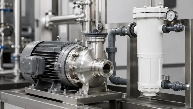
Centrifugal Pump – SS316L Wetted Parts, TEFC Motor, 1-15 hp
We use stainless steel 316L for all pump wetted components because the CIP circuit alternates between pH 2–3 acid solution and pH 11–12 alkaline solution, sometimes with chloride-containing chemistry. Standard 304L stainless and carbon steel components degrade under repeated acid cycling and chloride exposure. TEFC motor construction protects the motor from chemical humidity in the skid environment. Motor hp is project-specified based on cleaning circuit flow rate and vessel count.
Chemical Storage Tank – Conical-Bottom, Closed-Top, PE/HDPE or SS, 50-550 Gallons
The conical-bottom tank geometry is a functional requirement. Complete drainage of cleaning solution between stages prevents residual chemical from contaminating the next stage chemistry and ensures accurate concentration control. A flat-bottom tank that retains pooled alkaline chemical will dilute and partially neutralize the acid solution mixed for the subsequent stage. Standard sizing reference is 60 gallons, approximately 230 L, of cleaning solution per 8-inch pressure vessel housing six elements. This reference assumes a standard 8-inch pressure vessel with six spiral-wound RO/NF elements and typical external piping. Final tank capacity must include membrane vessel volume, pipework and hose volume, tank working volume, and minimum pump suction volume.
Cartridge Filter Housing – 5-20 Micron, Installed Between Chemical Tank and Membrane Array
The cartridge filter captures debris present in the cleaning solution before it reaches the membrane surface, including particulates introduced during chemical mixing, sediment from tank interior surfaces, and solids that precipitate when concentrated chemicals contact the mixing water. Replace according to filter housing DP limit or when DP rises by approximately 10–15 PSI during a cleaning cycle, whichever is more conservative; many operators replace the cartridge before each cleaning cycle as a precaution.
Structural Skid Frame – Carbon Steel Standard, SS304/316L Optional
The frame anchors the pump, tank, filter, instrumentation, and piping in a factory-tested, site-ready configuration. Membrane housings connect to the CIP circuit via flexible hose sets or fixed process piping depending on site layout and the number of vessels in the cleaning bank. Hose connections are standard for mobile or modular installations; fixed pipe connections are standard for permanent integrated skid installations.
| Parameter | Range / Options |
|---|---|
| Cleaning circuit flow rate | 20–210 gpm (1.8-48 m³/h), project-specified |
| Chemical tank capacity | 50-550 gal (190-2,080 L) |
| Tank material | PE/HDPE (standard), SS304/316L (optional) |
| Pump wetted parts | SS316L (standard) |
| Motor rating | 1-15 hp, project-specified |
| Cartridge filter micron rating | 5-20 micron |
| Vessel compatibility | 4-inch or 8-inch elements; 1-6 vessels per cleaning circuit *(Multi-stage RO/NF systems should normally be cleaned stage-by-stage to prevent foulant transfer between stages; confirm circuit grouping during engineering review.)* |
| Cleaning pH operating range | pH 2–3 (acid stage); pH 11–12 (alkaline stage) |
| Maximum cleaning temperature | 45°C standard; elevated temperature by materials review |
| Piping material | PVC (standard), CPVC or SS (optional) |
| Skid frame material | Carbon steel (standard), SS304/316L (optional) |
| Control type | Local manual panel (standard), PLC automation (optional) |
| Power supply | 220V/1Ph/50-60Hz or 380-460V/3Ph/50-60Hz |
The 60-gallon-per-8-inch-vessel sizing reference is only a starting point. Dense silica scale, long pipe runs, large dead-leg volume, or multi-vessel banks cleaned as one circuit can increase required solution volume and pump flow. We therefore size tank capacity and pump duty from the actual cleaning loop, not from membrane count alone.
PVC process piping is appropriate only when the selected cleaning chemical formulation, concentration, temperature, and exposure time are within PVC compatibility limits. CPVC, PP, PVDF, or SS piping should be reviewed for elevated temperature, oxidizing cleaners, aggressive chemical packages, or pharmaceutical-grade service.
Standard and Optional Equipment
Our CIP skids ship with the standard package below. Optional items are specified during engineering review based on application, site conditions, and downstream process requirements.
| Item | Standard | Optional |
|---|---|---|
| SS316L centrifugal pump with TEFC motor | ✓ | — |
| Conical-bottom, closed-top PE/HDPE chemical tank | ✓ | — |
| 5-20 micron cartridge filter housing | ✓ | — |
| Flow meter | ✓ | — |
| Pressure gauge (skid outlet) | ✓ | — |
| Temperature indicator | ✓ | — |
| Low tank level shutdown switch | ✓ | — |
| Manual recirculation and drain valves | ✓ | — |
| Local manual control panel | ✓ | — |
| PVC process piping | ✓ | — |
| Carbon steel skid frame | ✓ | — |
| pH monitor / controller | — | ✓ |
| Conductivity monitor | — | ✓ |
| PLC automation with programmable sequence control | — | ✓ |
| Variable frequency drive (VFD) on pump motor | — | ✓ |
| Immersion heater + thermostat (chemical tank) | — | ✓ |
| CPVC piping (acid/alkaline service upgrade) | — | ✓ |
| SS304/316L piping | — | ✓ |
| SS304/316L chemical tank | — | ✓ |
| SS304/316L skid frame | — | ✓ |
| Caster wheels (mobile / wheeled installation) | — | ✓ |
| Hot-water sanitization circuit (materials review required) | — | ✓ |
Control valves on the RO train, including isolation valves on feed, permeate, and concentrate lines, are reviewed as part of CIP integration planning. In systems with multi-port control valve assemblies on the RO skid, the CIP circuit can often be connected through existing valve positions without installing additional manual isolation valves. We confirm valve integration requirements during engineering review when the RO system configuration is provided.
PVC process piping is appropriate only when the selected cleaning chemical formulation, concentration, temperature, and exposure time are within PVC compatibility limits. CPVC, PP, PVDF, or SS piping should be reviewed for elevated temperature, oxidizing cleaners, aggressive chemical packages, or pharmaceutical-grade service.
CIP Membrane Cleaning Systems by Industry Application
CIP cleaning system requirements differ by application because dominant fouling type, tolerable cleaning frequency, chemical protocol, and material compatibility requirements are not uniform across industrial sectors. The table below is our standard application routing reference.
| Industry / Application | Dominant Foulant | Typical CIP Frequency | Protocol and Specification Note |
|---|---|---|---|
| Pharmaceutical and electronics ultra-pure water | Biological, organic | Tighter monitoring threshold per GMP protocol | May require hot-water sanitization circuit; piping, gaskets, and pump seal materials must accommodate elevated temperature operation. See deionized water filtration system design criteria. Final compliance must be confirmed against the user’s process specification, validation protocol, and applicable local standard. |
| Power generation and boiler feedwater | Silica, iron scale | Higher acid-cycle frequency in high-recovery RO service | Silica solubility is temperature- and pH-sensitive; acid cycle contact time and solution volume require specific sizing for dense silica scale. See boiler feed water treatment RO system design. |
| Municipal and seawater desalination | Biofouling, colloidal | Seasonal variation; monitor SDI trend for schedule adjustment | Large-flow systems require 8-inch elements and multi-vessel cleaning circuits; alkaline-dominant protocol with biofouling intensification in warm-water seasons. |
| Food and beverage production | Organic, biological | Frequency driven by regulatory sanitation schedule in addition to performance triggers | CIP chemical compatibility with food-grade standards must be confirmed; sanitation step is a mandatory addition to the standard CIP sequence. |
| Industrial wastewater reuse | Mixed organic and inorganic | Unpredictable; continuous DP and SDI monitoring required | Alkaline-first protocol is the default for mixed fouling; pre-treatment adequacy, coagulation, filtration, and SDI management, is the most critical variable affecting CIP frequency. |
Pharmaceutical and high-purity electronic water systems require the most specific CIP configuration review. Hot-water sanitization circuits, where the cleaning loop must sustain elevated temperature without degrading piping, gaskets, or pump seals, are available as a specific configuration option. We identify the hot-water sanitization requirement at the start of engineering review when the downstream application is declared as pharmaceutical or biopharmaceutical. Final compliance must be confirmed against the user’s process specification, validation protocol, and applicable local standard.
Boiler feedwater RO systems operating at high recovery rates generate accelerated silica and iron scale on membrane surfaces. For these systems, acid cycle frequency is typically higher than in municipal service, and the CIP skid must be sized for the acid solution volume and contact time required to dissolve dense calcium-silica or iron oxide scale deposits, not sized to the same formula as a light-industrial system of equivalent vessel count.
Qingdao Hiju Thermal Power Co., Ltd
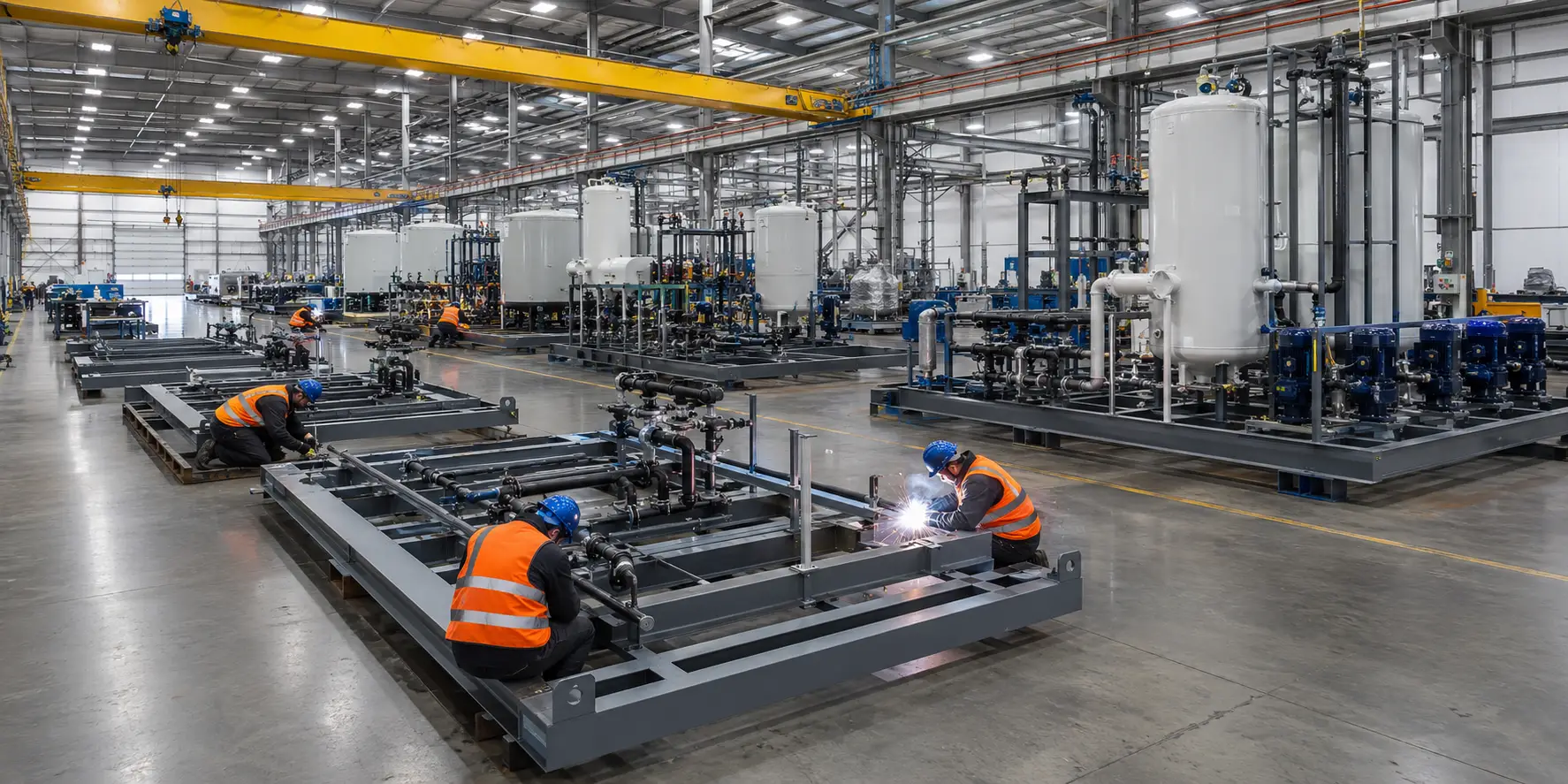
Established in 2016, Qingdao Hiju Thermal Power Co., Ltd designs, fabricates, and factory-tests CIP membrane cleaning systems alongside RO membrane elements, pressure vessel housings, control valves, and complete water treatment systems, all within a single vertically integrated production facility. Our CIP skids are exported to 20+ countries and regions. OEM and ODM manufacturing is available for system integrators sourcing CIP equipment for inclusion in branded or custom-configured water treatment packages for export.
CE documentation and ISO 9001 certification are standard with our export shipments. ASME-related documentation scope is reviewed during order design for applications where pressure vessel or system certification is required. Customers are encouraged to confirm applicable certification scope for their specific market and end use.
For technical inquiries and project reviews, contact us via our online inquiry form, WhatsApp, or email. Include the sizing parameters listed above so our engineering team can respond with a specific configuration review rather than a general product description.
Certification & Documentation Scope
| Item | Scope |
|---|---|
| ISO 9001 | Quality management system certification covering manufacturing and inspection processes |
| CE Declaration of Conformity | Applicable to electrical/control/skid package only; confirm by destination market before order |
| ASME | Applicable pressure vessels or pressure-rated assemblies only; available on request |
| Factory pressure and leak test | Pump, piping, tank drain circuit, filter housing, and valves tested before shipment |
| Electrical test | Motor, control panel, emergency stop, and low-level shutdown circuit verified |
| FAT report | Flow, pressure, recirculation, drainability, and instrumentation verification; available on request |
| Manual and P&ID | Supplied with every skid |
| Material certificates | SS316L pump and piping certificates available on request |
Inputs Required to Size Your CIP Cleaning System
Provide the following parameters and we will return a CIP membrane cleaning system specification, tank capacity, pump rating, motor size, vessel circuit configuration, standard and optional equipment recommendation, and shipping configuration, without requiring a site visit.
- Membrane type — RO, NF, UF, or MF
- Element size — 4-inch or 8-inch
- Elements per vessel and total vessel count in the membrane train to be serviced
- Current normalized performance readings — current permeate flow vs. 48-hour commissioning baseline; current differential pressure vs. baseline; current salt rejection
- Known or suspected fouling type — inorganic scale, organic, biological, colloidal, mixed, or unknown
- Feed water analysis report — if available: TDS, total hardness as CaCO3, silica, iron and manganese, TOC or BOD indicator, SDI
- Operating pressure range — normal RO feed inlet operating pressure
- Site power supply specification — voltage, phase, and frequency, for example 380V / 3Ph / 50Hz
- Installation type — fixed skid or mobile/wheeled; available floor footprint if constrained
- Downstream application — boiler feedwater, pharmaceutical, food and beverage, seawater desalination, industrial wastewater reuse, or other; and destination country and port of entry
For new plant design and procurement, items 3, 7, and 8 are available from the system design specification. For operating plants requesting CIP skid replacement or upgrade, items 4 and 5 are the most critical inputs. If fouling history is uncertain, we can recommend a fouling assessment approach based on feed water type, operating temperature, and pre-treatment records.