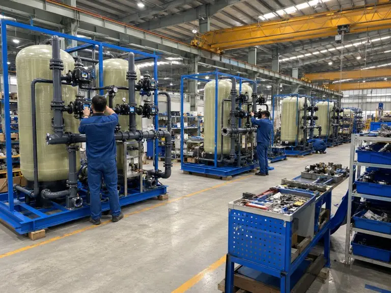
Double Valve Double Tank Water Softener
We build double valve double tank water softeners for projects where one shared valve cannot carry the required flow, regeneration logic, or maintenance boundary.
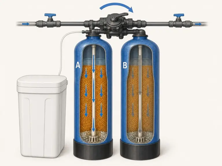
Each resin vessel has its own automatic valve and meter signal, so the system can run both tanks in parallel, regenerate one tank while the other stays online, and isolate one valve while the other tank continues supplying softened water at reduced single-tank capacity.
Two Valves Change the Operating Logic, Not Just the Tank Count
A shared-valve design can alternate vessels, but it cannot make two tanks behave as two independently controlled softening units. The DVDT configuration changes service flow, regeneration timing, and maintenance isolation.
| Capability | Single-Valve Single-Tank | Single-Valve Double-Tank | Double Valve Double Tank |
|---|---|---|---|
| Continuous service during regen | No | Yes | Yes |
| Combined parallel flow mode | No | No | Yes |
| Independent regen trigger per tank | No | No | Yes |
| Per-tank fault isolation | No | No | Yes |
| Maximum available flow | One tank | One tank | Two tanks in parallel |
A single valve single tank water softener stops softened-water service during its 60–90 minute regeneration cycle. A single-valve double-tank unit solves downtime by alternating between tanks through one shared valve, but it still cannot exceed one tank’s design flow rate, and a shared-valve fault affects both tanks simultaneously.
In our DVDT configuration, each tank has its own programmed valve, meter input, and regeneration sequence. This produces parallel service mode where both tanks supply treated water together, and alternating mode with independent regen scheduling where one tank regenerates while the other carries full demand.
Within our full range of water softener systems, this is the configuration we review when the buyer needs both higher flow and independent valve redundancy.
Recommendation boundary
We recommend the double valve double tank configuration when design flow exceeds one tank’s stable service velocity, when a shared-valve fault is an unacceptable shutdown risk, or when regeneration must happen without reducing the plant below its required softened-water flow.
Operating Logic: Parallel Service and Independent Regen Trigger
In a double valve double tank water softener, we use the same two vessels in different operating states: both tanks can share service flow in parallel, then one tank can leave service for regeneration while the other remains online.
Service Phase — Parallel Mode
In parallel service, both tanks receive feed water and each resin bed removes calcium and magnesium hardness at the same time. We design each tank for a resin bed service velocity we normally review in a conservative range around 8–15 m/h for stable operation. Pushing above this range increases channeling and can cause hardness breakthrough before the meter trigger fires.
When a project asks for 80 m³/h and one practical vessel can only carry 40 m³/h at the correct bed velocity, the double-valve layout lets both tanks operate together instead of forcing one oversized vessel or excessive service velocity.
Resin Exhaustion and Independent Regen Trigger
When Tank A’s flow meter reaches its preset treated-water volume, Tank A’s valve starts regeneration. Tank B keeps supplying full demand during Tank A’s cycle; when Tank A completes rinse and returns to service, parallel flow is restored, and Tank B’s trigger fires later from its own meter reading.
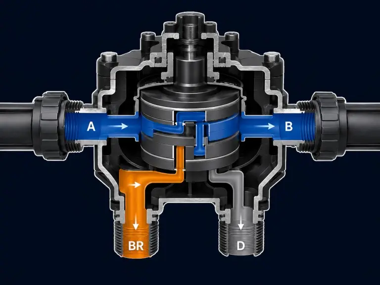
Backwash
10–15 min. Upflow expands the resin bed, releases compacted fines, and sends trapped suspended solids to drain.
Brine Draw
20–30 min. The injector draws NaCl solution so Na⁺ ions displace accumulated Ca²⁺ and Mg²⁺ from resin sites.
Slow Rinse
20–30 min. Reduced-velocity flow completes brine displacement and pushes residual brine through the bed to drain.
Fast Rinse
10–15 min. Fresh water flushes the resin bed at service velocity before the tank returns to softened-water duty.
Regeneration duration
Total regeneration time for a standard industrial vessel is usually 60–90 minutes. Tank B supplies demand throughout Tank A’s cycle.
When to Specify a Double Valve Double Tank System
We treat DVDT as an engineering decision, not an automatic upgrade; the table below shows the conditions that justify the extra valve, controls, and commissioning complexity.
| Condition | Consequence If Under-Specified | DVDT Solution |
|---|---|---|
| Design flow rate exceeds single-tank capacity | Service velocity rises above the resin bed’s stable range, causing channeling and early hardness breakthrough. | Both tanks can operate in parallel so combined flow is split across two resin beds. |
| Zero regen downtime required | A single-tank system stops producing softened water for 60–90 minutes during regeneration. | One tank can regenerate while the other remains in service, then the system returns to parallel flow. |
| High peak-to-base flow variation | Sizing only for average demand underserves shift overlap, boiler makeup spikes, or hotel morning/evening peaks. | Parallel mode covers peak periods; independent volume triggers schedule regen after each tank’s actual loading. |
| Per-tank valve redundancy required | A shared valve fault takes both vessels offline at the same time. | Tank A’s valve can be isolated while Tank B continues supplying treated water at its individual capacity. |
When DVDT Is Not the Right Choice
Inlet Iron Exceeds 0.3 mg/L Without Upstream Iron Removal
Iron fouling of SAC resin is progressive and standard NaCl brine regeneration cannot remove iron hydroxide deposits from exchange sites. For iron above 0.3 mg/L, we require upstream iron removal before accepting the softener design.
Turbidity Above 5 NTU Without Pre-Filtration
Suspended solids compact on the resin bed surface, raising differential pressure and reducing effective bed depth. A multimedia filter or cartridge filter is required upstream when inlet turbidity exceeds 5 NTU.
Free Chlorine Above 0.1 mg/L
Residual chlorine oxidizes the sulfonyl exchange groups on SAC resin and reduces exchange capacity over time. We include granular activated carbon or sodium bisulfite dosing when free chlorine exceeds 0.1 mg/L.
Flow Demand Requires More Than Two Parallel Tanks
When two FRP vessels cannot supply the design flow at correct service velocity, a larger manifolded configuration is required. Our multi tank water softener are the correct step-up.
Space or capital constraints may favor a shared-valve design. Our single valve double tank water softener achieves zero-downtime alternating service with one shared control valve at lower hardware cost when the design flow fits a single tank’s capacity.
Double Valve Double Tank Water Softener Specifications
Parameters marked ⊕ require project-specific data or a water analysis to finalize. We use these inputs during our initial technical review before issuing any sizing recommendation.
| Parameter | Specification or Range | Note |
|---|---|---|
| Inlet hardness | Up to 450 mg/L as CaCO₃ (25°dH) | ⊕ Requires water analysis; above 300 mg/L, regen frequency and brine demand increase — see specification mistakes section above. |
| Output hardness target | ≤75 mg/L as CaCO₃ (design target); Lower outlet hardness targets are reviewed by inlet chemistry, service loading, resin volume, salt dose, and regeneration mode. Not quoted as an unconditional value | Stated as design target, not a guaranteed value — confirmed after water analysis and resin loading review. |
| Design flow rate | DVDT systems are reviewed from approximately 5 m³/h per tank upward. Combined parallel flow is calculated from the selected tank pair | ⊕ We confirm bed service velocity before accepting the combined flow. |
| Operating pressure | 0.3–0.6 MPa (43–87 psi); max 0.8 MPa (116 psi) | ⊕ Feed pump and valve rating are confirmed against site pressure. |
| Temperature range | 5–40°C (41–104°F) | 40°C is the hard operating limit for standard SAC resin unless a special resin grade is selected. |
| Tank material | FRP pressure vessel or carbon steel lined vessel | FRP is standard; lined steel is reviewed for large industrial diameters. |
| Control valve | Two independent automatic control valves | Each valve controls its own tank, meter signal, and regeneration sequence. |
| Resin type | Strong acid cation resin, sodium form | Food-grade or application-specific SAC resin documentation can be reviewed. Final suitability depends on the buyer’s process-water standard, material traceability, and downstream treatment train. |
| Regeneration trigger | Volume-based / time-based / hardness sensor | ⊕ Volume-based triggering is our default for variable industrial demand. |
| Regeneration mode | Co-current or counter-current | Counter-current mode improves outlet hardness control at the same salt dose when the target is stringent. |
| Salt type | NaCl: solar evaporated, rock salt, or vacuum evaporated | ⊕ Salt form is selected from site supply availability and brine tank maintenance preference. |
| Brine tank capacity | 200–1,000+ kg salt storage | Sized from both tanks’ resin volumes, regen frequency, and salt delivery interval. |
| Control system | Timer controller standard; PLC + HMI available | PLC control is used when plant automation, alarms, or remote monitoring are required. |
| Power supply | 220V or 380V AC; 50Hz or 60Hz | ⊕ Destination electrical standard must be confirmed before cabinet fabrication. |
| Connection size | DN25–DN100 flanged or threaded | ⊕ Port size follows design flow, allowable pressure drop, and pipe standard. |
| Pre-treatment limits | Iron <0.3 mg/L; turbidity <5 NTU; free chlorine <0.1 mg/L | Iron removal, multimedia filtration, activated carbon, or chemical dechlorination is added if any threshold is exceeded. Internal review triggers; actual thresholds confirmed from resin supplier data and project water analysis. |
Where Hardness Excursions Have Measurable Industrial Consequences
Water hardness is not a uniformly tolerable variable. In some applications, a 60-minute regeneration excursion has little effect; in others, calcium carbonate scale creates direct downtime, cleaning cost, or product-quality risk.
Boiler Feedwater Pre-Treatment
Feed water above about 75 mg/L CaCO₃ can scale heat-transfer tubes and accelerate tube fatigue. Boiler specifications routinely require continuous softened supply with no hardness breakthrough during regeneration. We schedule DVDT alternating-mode regen against inlet hardness, hourly feedwater volume, boiler pressure, and makeup rate. For the full pre-treatment sequence, see our boiler feed water treatment overview.
Cooling Tower Makeup Water
At 3–4× concentration, 150 mg/L inlet hardness becomes 450–600 mg/L in recirculating water. High-ambient regions in the Middle East and Southeast Asia often need higher makeup volume because evaporation is faster. We use parallel service for peak cooling demand and schedule regeneration during lower overnight load.
Chemical and Pharmaceutical Process Water
Pharmaceutical-adjacent process water may require hardness below 5 mg/L as CaCO₃ through the full service cycle. We set volume triggers conservatively so late-cycle leakage does not reach the process line. Counter-current regeneration and food-grade resin are reviewed when the water contacts product or validated cleaning circuits. Final compliance must be confirmed against the user’s process specification, validation protocol, and applicable local standard.
Hotel and Commercial Building Water Systems
Morning and evening occupancy peaks can double the short-window demand compared with average daily consumption. Parallel service covers high hot-water and cooling-coil demand, while late-night alternating regeneration protects continuity. Our water filtration systems for commercial use packages use this logic when 24-hour service matters.
Regeneration Logic and Brine System Design
In our double valve double tank water softener configuration, two independent valves still share one salt-handling system, so the brine tank, injector draw rate, salt reserve, and regeneration flow direction must be sized as part of one operating package.
Brine Tank and Salt System
The brine tank stores bulk sodium chloride and maintains saturated brine at roughly 26% NaCl in the brine well. After each regen draw, the brine maker refills the drawn volume with fresh water so additional salt dissolves before the next cycle.
We deliver diluted brine to the resin bed at the injector inlet, typically 8–12% NaCl, and size the brine tank from both resin volumes, expected regeneration frequency, and site salt delivery interval. Salt storage capacity for DVDT systems commonly ranges from 200 kg to more than 1,000 kg.
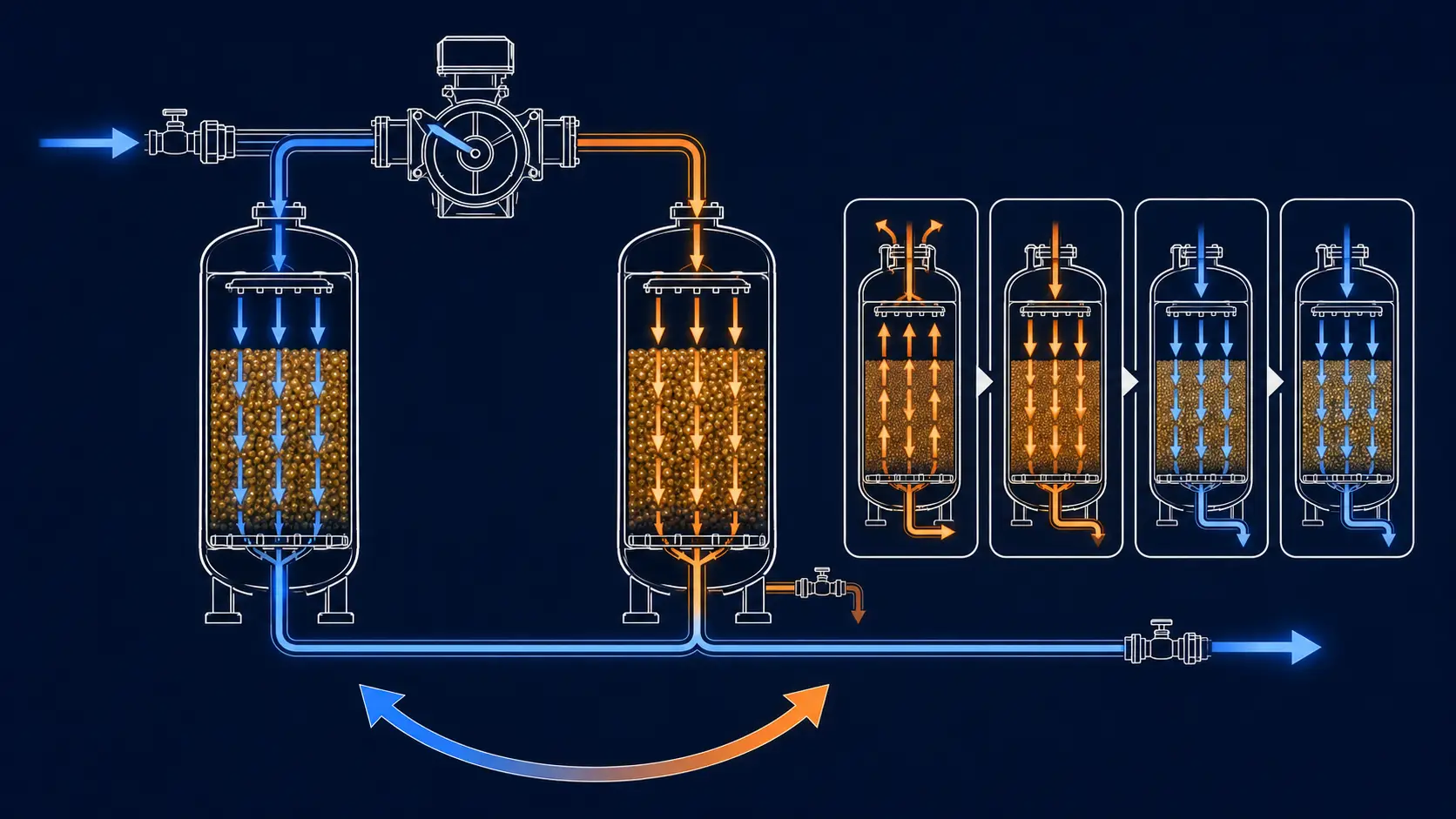
Co-Current Regeneration
Brine flows downward in the same direction as service flow, so the freshest brine contacts the most exhausted inlet zone first. This is simpler to commission and works for many industrial targets, but outlet hardness leakage is higher at the same salt dose than counter-current operation.
Counter-Current Regeneration
Brine flows upward, opposite to service flow, so the freshest brine contacts the outlet end of the resin bed. We recommend this mode when the outlet hardness target is below 20 mg/L CaCO₃ or when salt cost makes regeneration efficiency a major operating variable.
Common Specification Mistakes at the Review Stage
These mistakes usually appear before purchase, not after installation; we check them during inquiry review because they affect resin volume, valve selection, regeneration timing, and control cabinet design.
Sizing to average daily consumption
A facility using 500 m³/day is not automatically a 21 m³/h system. If production runs 16 hours with shift overlap, peak demand can reach 40–50 m³/h, which changes the required bed area and valve capacity.
Treating 450 mg/L as a universal hard limit
Above about 300 mg/L CaCO₃, resin exhaustion accelerates, regeneration becomes more frequent, and brine waste rises. Near 400–450 mg/L, we may review lime pre-softening or split-flow design before accepting standard SAC resin loading.
Omitting the regeneration window
If the plant requires full parallel flow during shift hours, tank volume must be sized so no tank triggers regeneration inside that restricted window. Without this constraint, a preliminary design may need upsizing later.
Requesting PLC control without site standards
A PLC panel must match 220V/50Hz, 380V/50Hz, 60Hz supply, and the plant’s communication protocol. We confirm power and automation requirements before the cabinet is built and factory-tested.
Sizing Inputs for Correct System Configuration
We do not issue a configuration recommendation or preliminary quotation without reviewing the inputs that affect resin volume, tank sizing, valve selection, brine capacity, and regeneration schedule.
Raw water analysis
Hardness as CaCO₃ or °dH, TDS, iron, turbidity, pH, and free chlorine.
Output hardness target
≤75, ≤20, or ≤5 mg/L CaCO₃ each changes resin loading and trigger settings.
Design and peak flow
Average m³/h and peak demand decide whether parallel mode is required.
Operating schedule
Daily hours, shift overlap, and restricted regen windows define usable cycle length.
Preferred regen trigger
Volume, time, or hardness-sensor trigger; volume-based is our industrial default.
Power supply
220V or 380V AC, 50Hz or 60Hz, and any PLC or communication standard.
Destination country
Import standard, CE or ASME documentation need, and market electrical practice.
Application type
Boiler, cooling tower, food, pharmaceutical, building service, or process water.
Send your water analysis before price comparison.
Partial data is workable, but it produces a wider estimate range until the missing hardness, flow, and regeneration constraints are confirmed.
Manufacturing and Quality
We design, assemble, and factory-test double valve double tank softening systems at our Qingdao facility before export shipment.
2016
21,000 sqm
28 engineers
OEM/ODM