
Self Cleaning Filters for Continuous Industrial Water Treatment
Our self cleaning filter units are designed to maintain downstream flow during normal automatic cleaning — no system shutdowns, no replacement cartridges, and no operator required. Each automatic backwash filter maintains inline mechanical straining at your specified micron rating while the automated cleaning cycle removes accumulated solids and routes them to drain. Applications requiring uninterrupted flow under all conditions should review duplex or bypass arrangements.
10–1,000 μm filtration precision / standard units and parallel manifold configurations sized from project flow requirements / ΔP or timer-triggered cleaning cycle. These units fit within our broader range of industrial water treatment equipment.
When to Specify a Self Cleaning Filter
The decision to specify an automatic backwash filter over a manual or cartridge alternative comes down to four operating conditions. Review the criteria below; if your application does not match the right-fit column, we will route you to the more appropriate equipment class before you spend time on a configuration review.
Right-Fit Conditions
- As an economic screening rule, flow rate exceeds 50 m³/h and scheduled manual cleaning requires process isolation.
- Inlet suspended solids are high or variable: seasonal surface water, open cooling tower circuits, or raw river water.
- No reliable on-shift staffing is available for manual element service.
- Downstream equipment cannot tolerate brief unprotected intervals, including RO membranes, heat exchanger tubes, and precision emitters.
- Operating cost comparison between self-cleaning and replaceable-element filtration is part of the review.
Consider an Alternative
- As an economic screening rule, flow below approximately 10 m³/h: stainless steel cartridge filter housing may be more practical where manual maintenance is manageable.
- Dissolved contaminants such as chlorine, organics, TDS, or hardness are not captured by a screen. Use activated carbon water filter for chlorine and organics, or multi media filter for broad suspended solids removal.
- Inlet TSS is very low and sustained, making automated backwash harder to justify.
- Required precision falls below 10 μm on a sustained basis.
Fine-end boundary: Standard wedge wire and mesh screen elements for auto backwash filter service operate reliably from 10 to 1,000 μm. When your sustained filtration requirement falls below 10 μm, we assess whether a disc filter or membrane pretreatment stage is more appropriate than a screen-based backwash unit.
How the Automatic Cleaning Cycle Works
The operating mechanism of a self cleaning filter is mechanical straining followed by a hydraulically driven flush; the cleaning event is seconds-scale, and the unit is designed to maintain downstream flow during normal automatic cleaning.
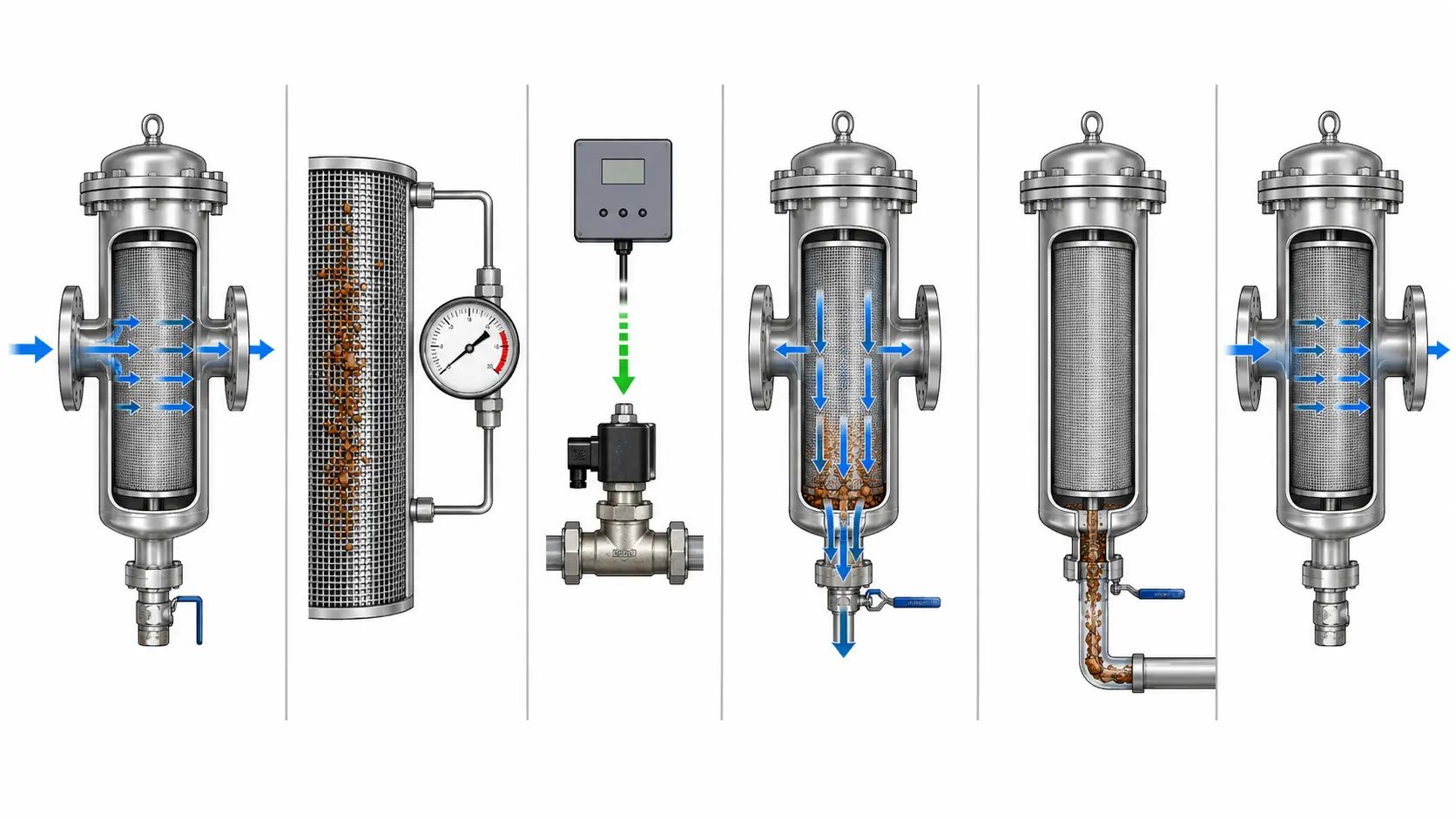
Filtration
Feedwater enters and flows through the element. Particles larger than the rated opening accumulate on the upstream face while filtered water continues at full operating pressure.
ΔP Buildup
As particle loading increases, resistance rises and differential pressure across inlet and outlet climbs. The control unit monitors ΔP continuously.
Trigger
When ΔP reaches the setpoint — typically 0.05 MPa for RO pretreatment, up to 0.1 MPa for standard industrial — the control unit signals the flush valve. Timer backup protects low-flow periods.
Backwash Flush
The flush valve opens. Pressurized filtrate reverses through the element segment, dislodging accumulated solids while the remainder continues in service.
Solids Discharge
Dislodged solids discharge to drain through the backwash outlet. Volume per cycle is determined by element area, pressure, and cleaning frequency.
Return to Service
The flush valve closes and the cleaned element returns to filtration mode. The complete cycle runs without operator presence or process shutdown.
Automatic Backwash
Cleaning trigger: ΔP setpoint or timer
Downtime: designed for continuous flow during normal cleaning
Labor: none required
Consumable cost: no replacement elements
Cartridge / Manual Filter
Cleaning trigger: manual schedule or element differential
Downtime: process isolation required
Labor: element removal, cleaning or replacement, reinstall
Consumable cost: replacement elements at each interval
Self Cleaning Filter Configuration by Application
We configure each automatic backwash filter to the specific requirements of the application. The five variable categories below determine the unit specification; we confirm each during the configuration review before issuing a quotation.
Filtration Precision
For RO membrane pretreatment, 50–100 μm elements provide upstream coarse protection before finer cartridge filtration; this does not replace the final pre-RO security cartridge filter required by membrane manufacturer guidance. Cooling tower sidestream typically uses 100–300 μm, and irrigation networks commonly use 100–200 μm. Micron values refer to screen or mesh opening size; actual particle removal depends on particle shape, deformability, flow velocity, and element condition.
Filter Element Type
Wedge wire screen fits heavy particle loads, repeated high-pressure backwash cycles, and fibrous or abrasive particles. Fine mesh screen is standard for 10-200 μm precision. Sintered mesh fits chemical compatibility or elevated-temperature constraints, while perforated plate is used for coarse screening at 500 μm and above.
Housing Material
304 stainless steel fits standard fresh water where chloride content is low. 316L is commonly reviewed for saline, high-chloride, food-contact, or hygiene-sensitive applications. Final material selection depends on chloride concentration, temperature, pH, cleaning chemicals, product-contact classification, and buyer specification. Carbon steel with internal lining fits large-diameter cost-sensitive units where water chemistry is compatible.
Control Mode
Our standard configuration uses a standalone differential pressure switch with timer relay backup. For centralized process control, we supply PLC-ready units with 4-20 mA or digital I/O output for DCS or SCADA integration. Manual override is available at the controller.
Installation Orientation
Horizontal installation fits sites with limited overhead clearance. Vertical installation fits sites where floor space is constrained. Orientation affects drain line routing and element access direction, so we confirm it during configuration review.
Bypass Provision
We recommend confirming upstream and downstream isolation valves before installation. A bypass line allows inspection or unscheduled maintenance without total system shutdown. Confirm bypass scope during configuration review because it is a site-specific decision, not a default inclusion.
Where Automatic Backwash Filters Are Specified
Automatic backwash filters are specified across six primary application categories. The table maps each application to what the filter protects downstream, the filtration precision appropriate for that objective, and the key specification variable that determines the correct unit configuration.
| Application | What the Filter Protects Downstream | Typical Filtration Precision | Key Specification Variable |
|---|---|---|---|
| RO membrane pretreatment | Spiral-wound membrane feed spacers; suspended solids accelerate fouling and raise differential pressure across the membrane element. | 50-100 μm | ΔP trigger set conservatively at 0.05 MPa to respond before particle load accumulates at membrane inlet. |
| Cooling tower sidestream | Heat exchanger tube surfaces and tower fill; uncontrolled suspended solids cause scale-assisted biofouling and tube pitting. | 100-300 μm | Sidestream flow rate is a defined percentage of total tower circulation; confirm with cooling system design. |
| Irrigation network inlet | Drip emitters and sprinkler heads; particle clogging causes uneven distribution, flow rate drop, and crop damage. | 100-200 μm | Seasonal inlet turbidity variation determines cleaning cycle frequency and element sizing. |
| Industrial process water | Pumps, nozzles, heat exchangers, and product-contact surfaces in steel, paper, chemical, and power applications. | 50-500 μm | Operating pressure and fluid chemistry determine element type and housing material; provide water analysis. |
| Food and beverage pretreatment | CIP systems, process equipment, and product water circuits; particulate contamination affects product quality and equipment reliability. | 25-100 μm | 316L SS commonly reviewed for product-contact surfaces; seal material confirmed from fluid temperature and compatibility. Review alongside our food and beverage water treatment solution scope. |
| Municipal water pretreatment | Clarifiers, disinfection units, and distribution network equipment; coarse screening reduces chemical demand and maintenance. | 100-500 μm | High-flow applications above 500 m³/h typically require parallel manifold configurations; see our municipal and community drinking water solution scope. |
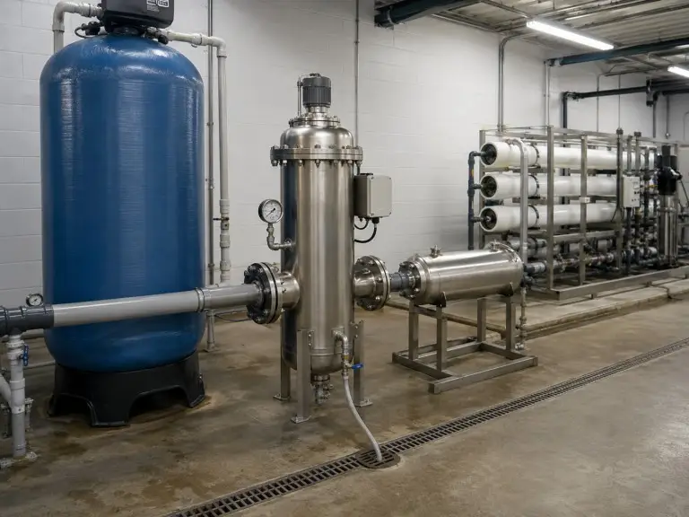
Operating Specification Reference
The table below maps key technical variables across the six principal application categories. Operating pressure sub-ranges and control mode recommendations are directional guidance based on typical application conditions and must be confirmed from your system design data during configuration review.
| Variable | RO Pretreatment | Cooling Tower | Irrigation | Industrial Process | Food & Bev | Municipal |
|---|---|---|---|---|---|---|
| Filtration precision | 50-100 μm | 100-300 μm | 100-200 μm | 50-500 μm, process-specific | 25-100 μm | 100-500 μm |
| Operating pressure | Normally selected for pretreatment pressure upstream of RO high-pressure pump. Housing rating must exceed max operating and surge pressure. | 0.6-1.5 MPa; confirm sidestream circuit | 0.6-1.0 MPa; confirm network pressure | 0.6-2.5 MPa; from process P&ID | 0.6-1.5 MPa; confirm cleaning circuit pressure | 0.6-1.5 MPa; confirm distribution pressure |
| ΔP trigger setpoint | 0.05 MPa, conservative | 0.07-0.1 MPa, standard industrial | 0.05-0.1 MPa, emitter sensitivity | 0.05-0.1 MPa, process-specific | 0.05 MPa, conservative | 0.07-0.1 MPa, standard |
| Housing material | 304 or 316L SS; confirm Cl- and TDS | 304 SS standard; 316L if treatment raises Cl- | 304 SS for fresh water | 304 SS / 316L / CS with lining | 316L SS for product-contact surfaces | 304 SS or CS for large-diameter installations |
| Element type | Fine mesh screen | Wedge wire or fine mesh | Fine mesh screen | Wedge wire / perforated plate / fine mesh | Fine mesh or sintered mesh | Wedge wire or perforated plate |
| Control mode | PLC integration common; ΔP primary + timer backup | Standalone ΔP + timer; BMS if required | Standalone ΔP + timer; timer-primary at seasonal low flow | PLC / SCADA per facility standard | PLC with process cleaning sequencing input | SCADA integration standard |
| Connection standard | DN flange, ANSI / DIN / JIS | DN flange, ANSI / DIN / JIS | DN flange; confirm irrigation pipe standard | DN flange, ANSI / DIN / JIS | DN flange; confirm hygienic connection where applicable | DN flange per local piping code |
Common Mistakes and Engineering Boundaries
We review these five misspecification patterns regularly during inquiry stage. Identifying them early prevents equipment selection errors that delay system design and add cost to the treatment train.
Precision Without a Downstream Reference
We regularly receive inquiry forms requesting “a 100 μm filter” with no indication of what the filter is protecting. The downstream equipment specification, such as membrane model, heat exchanger tube diameter, or emitter orifice size, is the correct starting point.
Filtering a Dissolved Contaminant Problem
Screen-based mechanical filtration targets suspended solids captured by a physical barrier. It has no effect on TDS, hardness, dissolved chlorine, organics, or colloidal turbidity below the rated opening, so we route those inquiries to the correct treatment step.
Undersized Backwash Drain Capacity
The backwash discharge line must carry intermittent pressurized flow to a drain point capable of receiving it. If drain routing is restricted or above grade, gravity drain may not be practical and pressurized drain lines are required.
Single Unit Where a Manifold Is Needed
For flow rates above approximately 500-1,000 m³/h, one large housing may not be optimal. Parallel manifold configurations with staggered cleaning cycles maintain flow during backwash and allow individual units to be isolated for inspection.
No Upstream Coarse Screening at High Inlet TSS
As a preliminary review trigger, when sustained inlet TSS exceeds approximately 200–500 mg/L, or when the source includes leaf matter, fibrous material, or large sediment, an upstream coarse strainer protects the element. Actual threshold depends on element type, solids nature, cleaning frequency, and drain capacity.
How We Catch These Before Quotation
Every inquiry goes through a configuration review before we issue a specification recommendation. We check water analysis, downstream equipment type, flow rate, drain conditions, and site constraints before confirming element type, housing material, ΔP trigger, and control mode.
Why Hiju Engineering
Qingdao Hiju Thermal Power Co., Ltd has designed and manufactured water treatment filtration equipment since 2016. Our self cleaning filter units are manufactured under CE and ISO 9001 documentation scope; ASME-code pressure vessel documentation is available on request for projects requiring it.
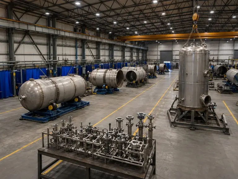
70,500 sqm
Factory
21,000 sqm
Workshop
28 + 78
Engineers + technicians
20+
Export countries
Manifold Design for High-Flow Installations
Above approximately 500–1,000 m³/h, a single filter housing may not be optimal. Our engineers design parallel manifold systems with staggered cleaning cycles, so each unit cycles in turn while the remaining units stay in service.
Cooling Tower Chemical Compatibility
For cooling tower protection in hot-climate markets, our team reviews chemical treatment compounds alongside housing material selection to confirm whether 304 or 316L stainless steel is appropriate given expected Cl⁻ concentration.
Configuration Review Checklist
Every inquiry goes through a configuration review before we issue a specification recommendation.
- Water analysis — TSS, turbidity, pH, temperature, chloride
- Downstream equipment type — RO, cooling tower, irrigation, process, F&B, municipal
- Design flow rate — m³/h; peak and average if variable
- Required filtration precision — µm and rationale (what is being protected)
- Operating pressure — supply pressure and allowable pressure drop
- Drain conditions — discharge route, gravity vs. pressurized, drain capacity
- Site constraints — orientation, clearance, footprint, control interface
- Project destination and certification scope — CE, ISO 9001, ASME if required