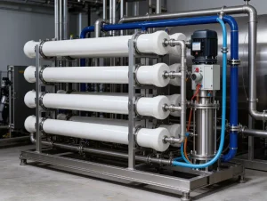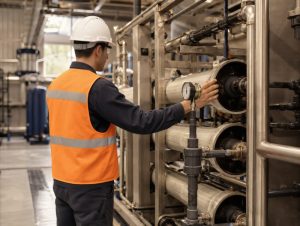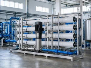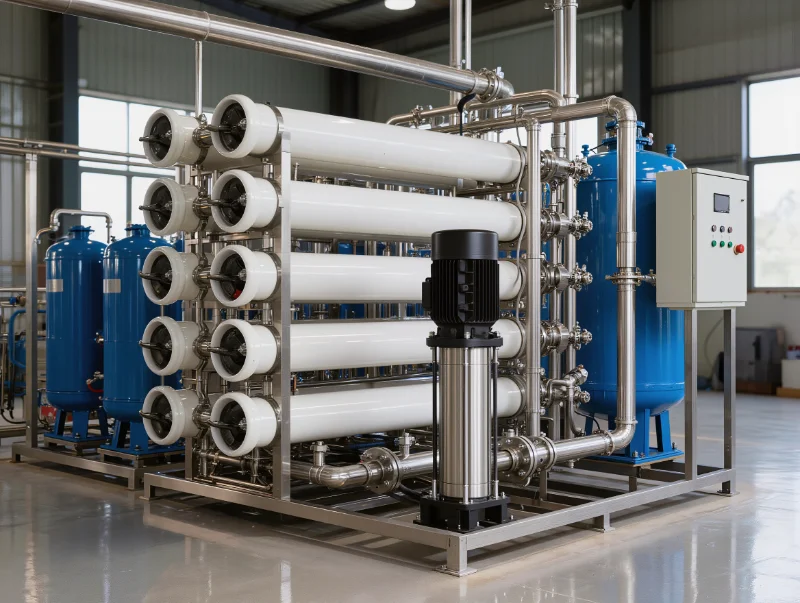
An industrial reverse osmosis system is built from four groups of components: pretreatment, core separation, post-treatment and storage, and instrumentation and controls. Pretreatment covers multimedia and carbon filters, softening or antiscalant dosing, and cartridge filters. The core stage is the RO membranes, pressure vessels, and high-pressure pump. Which parts you need is not fixed. It depends on the source water: the TDS, hardness, SDI, and free chlorine. The permeate quality and recovery rate you target also shape it. We size each group from a measured feed-water report, since the same four groups look different on city water, a brackish well, or seawater.
The Component Set of an Industrial Reverse Osmosis System
An industrial reverse osmosis system groups its components into four blocks, sized to the feed water and the duty it must meet. The four blocks are pretreatment, core separation, post-treatment and storage, and instrumentation. Most buyers picture only the membrane and the pump. Those are just the core stage. A working plant also needs the pretreatment that protects that stage. It needs the instruments that show whether the plant is performing.
| Component group | Typical parts | Function | Primary selection driver |
|---|---|---|---|
| Pretreatment | Multimedia filter, activated carbon, softener or antiscalant dosing, cartridge filter | Removes particles, chlorine, and hardness before the membrane | Measured feed water: turbidity/SDI, free chlorine, hardness |
| Core separation | RO membranes, pressure vessels (membrane housings), high-pressure pump | Applies pressure and separates dissolved salts from the feed | Feed TDS and water type, required flow, target recovery |
| Post-treatment & storage | Remineralization, UV or ozone, EDI/DI, storage tank, distribution pump | Adjusts final water quality and holds or delivers permeate | End use: drinking, ultrapure, or process water |
| Instrumentation & controls | Conductivity/TDS meters, pressure and flow gauges, PLC panel, CIP system | Monitors, protects, and cleans the plant in operation | System scale, automation level, cleaning needs |
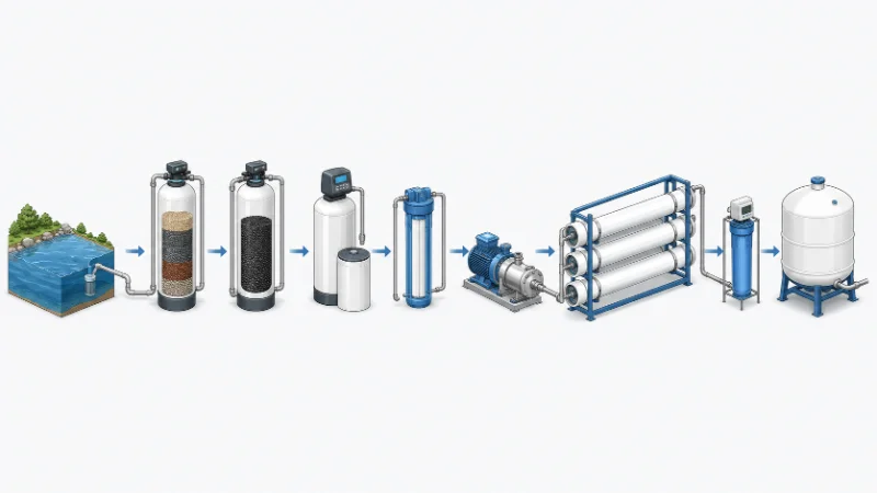
We align all four blocks to a single source-water report, rather than specifying them in isolation. A change in feed quality rarely touches only one block. Take a high-hardness feed. It changes the pretreatment, lowers the recovery the membrane can sustain, and may add an antiscalant dosing skid. The blocks are confirmed together, against the same analysis.
The Pretreatment Components That Determine Membrane Life
Pretreatment components set RO membrane life more than the membrane’s own datasheet does, because the membrane only tolerates the water it is fed. Many buyers treat the membrane as the part that matters and the pre-filters as an afterthought. That is the most common specification error we see. It usually shows up as fouling, which then gets blamed on the membrane.
Each pretreatment stage is chosen against a measured feed-water property, not added by default. Each parameter maps to a specific action, shown in the table that follows. The thresholds follow membrane manufacturer design guidelines. You confirm them against the element you choose.
| Feed-water parameter | Design concern | Practical action |
|---|---|---|
| SDI₁₅ (silt density index, per ASTM D4189) | Colloidal and particulate fouling | Multimedia or UF, then cartridge filtration; target SDI₁₅ below about 5 |
| Turbidity | Particle load on the membrane | Reduce below about 1 NTU before the membrane |
| Free chlorine / oxidants | Oxidation of polyamide (TFC) membranes | Dechlorinate with activated carbon filters or SMBS dosing; polyamide tolerates essentially none (commonly under 0.1 mg/L) |
| Hardness / alkalinity | Scaling on the membrane | Softening, antiscalant dosing, or pH adjustment |
| Silica | Scaling risk at high recovery | Recovery control, antiscalant, staged design |
| Iron / manganese | Fouling and oxidation deposits | Oxidation-filtration or dedicated removal |
| Temperature | Shifts flux, pressure, and scaling | Temperature-corrected design pressure |
Poorly matched pretreatment tends to cause early fouling soon after commissioning. The risk rises when SDI, oxidants, iron, biological load, or scaling potential sit outside the membrane supplier’s operating envelope. In brackish and high-TDS feed water, the cartridge and antiscalant stages usually foul first. They are the parts to re-check when permeate conductivity starts to climb. We match pretreatment to the measured chlorine, hardness, and SDI before we select the membrane. That way, the membrane only sees water it can handle.
Core RO Components: Membrane, Pressure Vessel, and High-Pressure Pump
The core of a reverse osmosis system is three components, each sized to the source water and the target output. They are the membrane, the pressure vessel that houses it, and the high-pressure pump that drives the feed. None of them can be chosen well until you characterize the feed water.
The RO membrane is the semi-permeable barrier that rejects dissolved salts. Its type is chosen for the water it will see: brackish-water, seawater, or low-energy elements for low-TDS supplies. Manufacturer datasheets usually state salt rejection in the high 90s percent, against a defined test solution. The figure a system holds in service depends on feed TDS, temperature, pressure, and membrane age. Treat the datasheet value as a starting point, not a guarantee for your water.
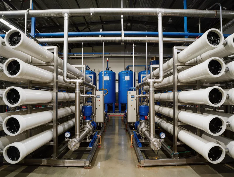
The pressure vessel, or membrane housing, holds the membrane elements in series and contains the operating pressure. The required flow sets the number of vessels and elements per vessel. The feed type sets the pressure rating, so seawater systems are rated higher than brackish ones. Most RO membrane housings are FRP (fiber-reinforced plastic) vessels. These are commonly specified to ASME BPVC Section X, which covers construction of fiber-reinforced plastic pressure vessels. Metallic vessels fall under ASME Section VIII, which covers pressure vessels in general. The right code depends on material, jurisdiction, and project specification.
The high-pressure pump overcomes the feed’s osmotic pressure and drives water across the membrane. Its duty is set by the source water and the recovery target. Under typical seawater RO conditions, operating pressure often falls around 55 to 70 bar. Seawater TDS generally sits in the 33,000 to 45,000 ppm range, and the pump has to overcome the osmotic pressure that follows. Brackish-water RO runs much lower. Final pump duty still depends on salinity, temperature, recovery, flux, fouling allowance, and the membrane model. Confirm it against a measured feed analysis rather than assume it. Suppose a membrane and pump are sized against a feed TDS that later proves too low. The plant then runs at higher pressure and lower recovery, and operators often read this as premature membrane wear rather than a specification mismatch. We check the resulting recovery against what the source water can sustain without scaling, before the array is fixed.
Post-Treatment, Storage, and Disinfection Components
Post-treatment and storage components are added according to the end use, not by default. A drinking-water system carries different parts than one feeding a pharmaceutical line. Permeate leaves the membrane clean, but often not in its final form. Each of these components answers a specific end-use requirement:
- UV or ozone disinfection — when the end use needs a microbiological barrier. RO reduces microbes but does not guarantee microbe-free water.
- Remineralization or pH adjustment — for drinking water, to restore taste and cut the corrosivity of very low-mineral permeate.
- EDI or DI polishing — for ultrapure uses such as pharmaceutical or electronics water, where permeate must reach high resistivity.
- Storage tank and distribution pump — when demand is intermittent. RO makes permeate at a steady, fairly slow rate, so an atmospheric tank has to be re-pressurized to deliver it.
We confirm which of these the target water standard requires. That keeps the plant from carrying post-treatment it does not need. A boiler-feed system and a bottling line can share the same core stage yet differ entirely in post-treatment. So we specify this group from the end use backward.
Instrumentation, Controls, and CIP Components
Instrumentation, controls, and cleaning components separate an industrial RO system from a packaged residential unit. They scale with the plant’s size and the level of automation required. On an industrial system, permeate conductivity or TDS monitoring is core instrumentation, not an optional extra. It is how an operator verifies that separation is holding.
Conductivity or TDS meters on the permeate track separation performance in real time. Pressure gauges across the pretreatment, feed, and concentrate lines catch fouling through rising differential pressure. Flow meters on the permeate and concentrate track recovery. An ORP sensor after dechlorination confirms that no oxidant is reaching the membrane. A PLC panel automates the dosing, flushing, and alarms. A clean-in-place (CIP) system circulates cleaning chemicals to recover membrane performance when it drops.
In industrial RO, CIP is triggered by normalized performance, not by the calendar. Membrane manufacturer guidelines point to cleaning when normalized permeate flow drops about 10 percent, salt passage rises about 5 to 10 percent, or the pressure drop rises about 15 percent. These readings move before water quality fails at the point of use. So a conductivity value that drifts upward is often the first sign that a membrane or pretreatment stage needs attention. We size the instrumentation and CIP components to the plant, so operators clean on condition rather than on guesswork.
Prioritizing Component Decisions for Your Source Water
The reverse osmosis component decisions to lock first are the source-water analysis and the pretreatment it drives. The membrane, pump, and recovery target are all sized from them. Once every component is on the table, the useful question is not which one is best. It is which decision constrains the others, and that is almost always the feed water.
The order that keeps a configuration correct runs downstream from the water. Characterize the source water first. It is the one input you cannot change, and it sets the requirements for everything else. Fix the pretreatment second, since that water dictates it and it protects the membrane. Select the membrane type and array third, for the now-known, pretreated feed. Size the pump duty and recovery target fourth, once the membrane and array are set. Source water comes first for one reason. A membrane or pump chosen before the feed is characterized is only a guess, and correcting that guess after commissioning is the costly part.
The same four groups resolve into different parts across source waters. A municipal feed may need only dechlorination and cartridge filtration ahead of the membrane. Well water often adds iron and manganese removal, plus softening. Brackish water needs antiscalant dosing and a staged design to reach useful recovery. Seawater needs seawater-rated elements, a high-pressure pump, and corrosion-resistant materials. The starting list is the same. The source water decides which parts a design actually specifies.
Selecting and sizing an RO system’s components is a separate task from the installation and piping design. That design is set by each site’s layout, footprint, and utilities, and it belongs to project engineering rather than component selection. We work downstream from the source-water report in that order. We model the scaling risk, fix the pretreatment, then confirm the membrane array, pump duty, recovery, and monitoring points against the real feed.
Conclusion
Specifying an industrial reverse osmosis system comes down to a short chain of decisions: source water, then pretreatment, then the membrane and pump sized for your recovery. The individual components all matter. But the order in which you confirm them is what keeps a plant from being over- or under-built.
We configure the pretreatment train against a measured source-water analysis before we size membranes or high-pressure pumps. A system sized against assumed feed quality, rather than a real analysis, is the most common reason a configuration has to be revised later. How the final plant looks still depends on project-level variables. These include feed temperature, seasonal water-quality swings, and the recovery you can sustain without scaling. All of them need confirming against your actual conditions.
Each component is pinned down by a specific input, so the useful next step is to send those inputs, not a general enquiry:
- A source-water analysis (TDS, hardness, SDI or turbidity, free chlorine, iron, and temperature) sets the pretreatment train and the membrane type.
- Required permeate flow and daily run hours set the vessel count and the pump duty.
- Target permeate quality and the application decide the post-treatment.
- Recovery target, feed pressure, and site utilities size the pump and frame the layout.
Give us those, and our industrial RO water systems come back specified at the component level for your water, not chosen off a shelf. The systems are built under ISO 9001 quality management and carry CE marking. Talk to our engineering team, or request a quote, to start.
FAQ
Replacement intervals depend on the component, the feed water, and how hard the plant runs. They are set by monitored performance, not by a fixed calendar. As a rough guide, membranes often last a few years, cartridge pre-filters change every few months, and media are replaced periodically. The real signal is a trend. Rising differential pressure or climbing permeate conductivity tells you a part needs attention. Tracking those readings tells you when to act, instead of swapping parts on a fixed schedule.
Whether a system needs added pressure depends on the source water’s osmotic pressure, the available feed pressure, and the target recovery. Seawater RO always needs a high-pressure pump, because seawater’s osmotic pressure is high. A brackish or low-TDS feed with good line pressure may need much less. The pump is one of the last components to size. Its duty follows from the feed water and the membrane, so you define those first.
Core components are the ones a plant needs to run the separation and verify it: the membranes, the vessels, the high-pressure pump, basic pretreatment, and conductivity monitoring. Optional components are added only when the end use calls for them, such as UV, remineralization, or EDI. What sets the line is a single test: does the water have to do this at the point of use? A fixed parts list does not decide it.
Whether you soften, dose antiscalant, or do both depends on feed hardness, your target recovery, and whether you want to avoid on-site salt regeneration. A softener removes hardness ions before the membrane. An antiscalant instead lets the system run at higher hardness or recovery, by holding off scale on the membrane. High-recovery or high-hardness designs often use antiscalant, sometimes with softening ahead of it. You confirm the choice against the feed analysis and the target recovery.
A seawater RO desalination system needs seawater-rated membrane elements and a high-pressure pump for roughly 55 to 70 bar. It needs pressure vessels rated for that duty, plus corrosion-resistant materials on the high-pressure side. Pretreatment has to be robust, because seawater carries a high fouling and biofouling load. Larger plants often add energy recovery to cut power on the concentrate stream. The exact set still depends on the intake type, salinity, temperature, and target recovery.
Industrial RO systems house membrane elements in several pressure vessels arranged in an array. A dedicated high-pressure pump drives them, and a PLC runs the system with instrumentation and a clean-in-place loop. A home or under-sink unit is a compact stack of cartridge filters and one small membrane. It feeds a pressurized tank and a faucet, with no automated controls or CIP. The components share the same separation principle. They differ in scale, materials, control, and how they are maintained.