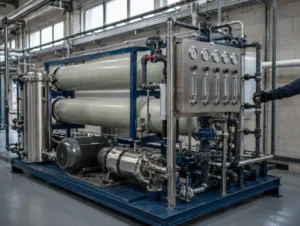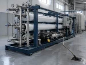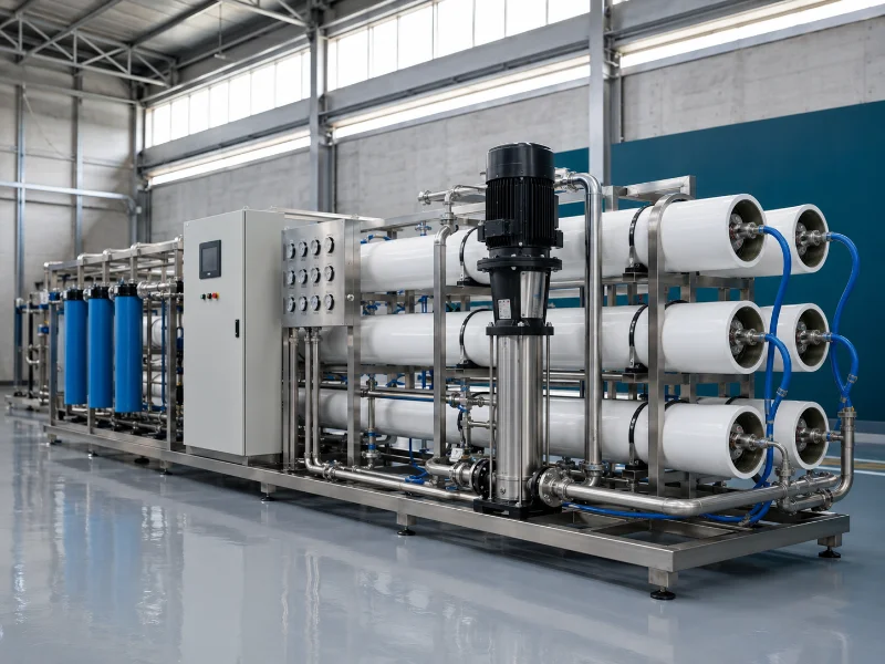
Brackish water reverse osmosis is reverse osmosis applied to feed water that sits between fresh water and seawater in dissolved solids. Which system that feed calls for depends less on the salinity label than on its scaling ions and the recovery the project needs. The U.S. Geological Survey generally places brackish groundwater between 1,000 and 10,000 mg/L, though published boundaries differ widely. A brackish water reverse osmosis system runs brackish-class membrane elements at moderate feed pressure. Pretreatment and scale control get sized from a full ion analysis, not from a TDS reading. Whether a specific well needs one depends on its hardness, silica, alkalinity and barium or strontium content as much as on its salinity.
Competing Definitions of Brackish Water
Brackish water is defined by a dissolved-solids band rather than a single threshold, and which band applies depends on whose classification a specifier works from.
| Source and context | Stated brackish band | What the boundary is based on |
|---|---|---|
| U.S. Geological Survey, brackish groundwater | 1,000–10,000 mg/L | Dissolved solids above fresh water, below seawater at roughly 35,000 mg/L |
| USGS salinity mapping zones | 10,000–35,000 mg/L classed as a transition zone, not as brackish | Resource mapping categories, not treatment routes |
| Other published definitions | 1,000 mg/L up to the seawater value | Brackish read as everything between fresh water and seawater |
| Supplier product pages, same category | Variously 1,000–10,000, 2,000–19,000, and 3,000–10,000 ppm | Product application limits |
| Membrane design references | Brackish elements intended up to roughly 4,000–5,000 ppm | Element operating envelope |
Read every band together with its origin. A classification band answers what to call the water. A product or element band answers what one specific machine can run. Neither answers the other’s question.
Supplier literature is the least consistent of those sources. Its figures may refer to different classification conventions, different membrane families, product limits, or different units. None of them is interchangeable without checking the context it was written for. One unit caveat matters when comparing sources: USGS notes that mg/L and ppm are equivalent below about 7,000 mg/L, above which a density correction applies.
Salinity Bands Versus System Specifications
A salinity band narrows the plausible membrane family for a feed, but it fixes neither operating pressure, achievable recovery, nor pretreatment, each of which follows from the specific ion mix. The one pressure figure worth anchoring to is public and checkable. Seawater at roughly 35,000 mg/L carries a natural osmotic pressure near 24 bar (350 psi), and applied pressure has to overcome that before any water crosses the membrane.
Scale that anchor down. Osmotic pressure rises roughly in proportion to dissolved ion concentration in a dilute solution. A 10,000 mg/L feed therefore sits near 24 × (10,000 ÷ 35,000), about 7 bar. Concentration at the membrane wall, temperature and pressure drop along the array all add to that figure, but not by an order of magnitude. For many conventional brackish feeds the arithmetic carries through to a conclusion product pages in this category rarely state. The recovery ceiling is set by concentrate-side scaling chemistry, not by the pressure rating of the elements.
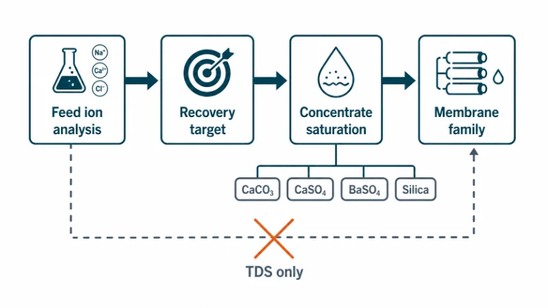
The qualifier matters, though. At the top of the brackish band, at low feed temperature, or where a very low permeate TDS is required, pressure and energy can turn decisive again. Membrane families also overlap enough that a high-salinity brackish feed is sometimes served by seawater-class elements.
The failure mode follows from the same logic. A system gets specified from a single TDS reading, and nobody checks the feed’s hardness, alkalinity and silica against concentrate-side saturation at the intended recovery. Scale then forms on the tail elements first. It shows up as rising differential pressure and falling permeate flow, and the fix is cleaning, a lower recovery, or the scale control that belonged in the design. None of that is visible in a salinity figure.
How Brackish Water Reverse Osmosis Works
Brackish water reverse osmosis works by raising feed pressure above the feed’s own osmotic pressure, which climbs with feed concentration and eases with temperature, so that water crosses a semi-permeable membrane while most dissolved ions stay behind. The recovery set point then decides how far above that floor the pump has to work. The membrane produces two streams: permeate at low TDS, and a concentrate carrying the rejected salt load.
Pretreatment on a brackish feed is shaped by which scaling species sits closest to saturation on the concentrate side. That is why two systems handling similar salinity can carry completely different front ends. Media filtration and cartridge filters handle suspended solids and turbidity, and residual chlorine comes out ahead of polyamide elements. Scale control then enters as antiscalant dosing, as softening, or as a lower recovery target, depending on whether carbonate, sulfate or silica is the binding species. Equipment selection and installation for those stages belong to a separate design document.
Downstream, a high-pressure pump raises feed pressure into the brackish operating range. Elements sit in stages so that crossflow velocity holds across the tail of the array as recovery rises. Permeate from any RO system is low in dissolved solids and weakly buffered, so pH stabilization, remineralization or disinfection get specified separately against the end use.
Brackish RO Against Standard and Seawater RO
The three RO families differ less in how they work than in the feed band each is built for, and the choice among them turns on feed chemistry and target recovery, not on capacity. Each family is also built around a different dominant risk.
| Typical membrane / application family | Commonly published feed band | Pressure regime | What actually decides the switch | Dominant risk |
|---|---|---|---|---|
| Tap-water / low-salinity RO | Under roughly 1,500 mg/L | Lowest | Feed is already fresh; RO polishes or removes a specific ion | Particulate fouling, chlorine damage |
| Brackish-water RO | Roughly 1,000–10,000 mg/L; supplier ranges quoted both lower and higher | Moderate | Concentrate-side saturation at the recovery required | Scaling on tail elements |
| Seawater RO | Typically applied approaching 35,000 mg/L, with a broad overlap zone below | Highest | Osmotic pressure at design recovery exceeds what brackish elements handle economically | Energy cost, high-pressure containment |
These are orientation bands, not engineering boundaries. Membrane families overlap: seawater-class elements run on high-salinity brackish feeds, low-energy elements at the low end. Check the final choice against element datasheets and a design projection run on the actual analysis, temperature, recovery and permeate target.
Two cases fall between the rows. A feed can sit numerically inside the brackish band and still suit a low-salinity system, where salinity is the only issue and recovery stays modest. A feed at the top of the band can behave like a seawater problem once the concentration factor at design recovery is applied. We compare those two edge cases directly instead of reading the family off the band, because the band is where both edges disappear.
Feed Water Variables Worth Confirming First
Two inputs should be confirmed ahead of all others on a brackish feed: a full ion analysis including the sparingly soluble species, and the recovery rate the site needs. Both come first because they decide other variables instead of being decided by them.
Recovery converts a feed analysis into a concentrate analysis. Whatever the array rejects stays behind in a shrinking volume, so concentration on the concentrate side climbs as the recovery target climbs.
| Recovery target | Idealized concentration factor, CF = 1 ÷ (1 − R) | Feed concentration of the controlling salt must stay below |
|---|---|---|
| 50% | 2× | one half of its saturation limit |
| 60% | 2.5× | two fifths |
| 70% | about 3.3× | about three tenths |
| 75% | 4× | one quarter of its saturation limit |
| 80% | 5× | one fifth |
| 85% | about 6.7× | about three twentieths |
Arithmetic only, with no allowance for salt passage, temperature or concentration at the membrane wall. Antiscalant dosing lets a system run above simple saturation, so the fractions above describe the no-additive case.
Real values sit near those fractions without landing on them, once salt passage, sampling variance and density changes are counted. The consequence holds regardless: a feed sitting below saturation for calcium carbonate, calcium or barium sulfate, strontium sulfate, or silica can still generate a concentrate that is not. The sparingly soluble ions set the recovery ceiling before TDS or capacity enter the calculation. A TDS range on a datasheet cannot tell anyone whether a system will hold the recovery it was sold on. Capacity, footprint and product-water target still matter, but they stay revisable on paper in a way a recovery target is not once the array is built.
Two published standards frame the analysis itself. ASTM D4195-23, a standard guide for water analysis for reverse osmosis and nanofiltration application, covers what a usable feed analysis should contain. ASTM D4189-23, the standard test method for silt density index, applies to relatively low-turbidity water below about 1.0 NTU and not to most RO or UF permeate. The method notes that SDI varies with temperature and with the membrane filter manufacturer. An SDI figure quoted without its test conditions is therefore not a specification, and values from different labs do not compare.
Re-sampling frequency should follow source variability, not an equipment interval: seasonal drawdown, nearby pumping activity, historical trend, and the consequence of leaving the design envelope. In coastal and inland well fields drawn down across a season or recharged unevenly, feed TDS and ion ratios shift first. A clear move in raw-water conductivity or in normalized permeate flow is the practical trigger to re-test. We verify which season an analysis was sampled in before treating it as the design case.
Where Brackish RO Fits and Where It Is the Wrong Tool
Brackish RO fits where a usable water source exists but carries too much dissolved salt for its intended use, and where removing that load is the point of the plant. Inland and coastal wells, deep boreholes and mildly saline surface sources feed process water, bottling and beverage lines, boiler makeup, irrigation, and community or hotel supply on that basis.
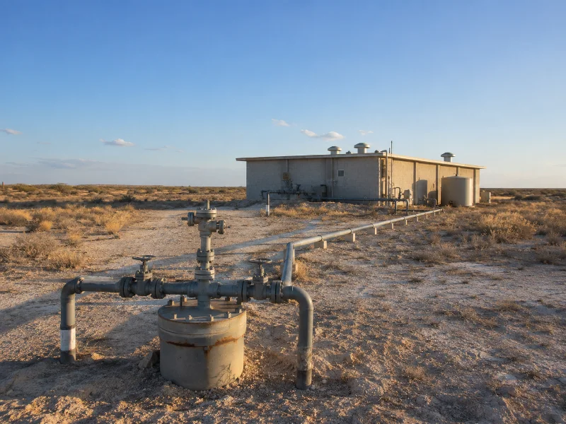
The lower edge deserves a direct statement. Where a well runs under about 1,000 mg/L and hardness, iron or taste are the only parameters limiting its use, a softener or an iron and manganese filter is usually cheaper, simpler and easier to operate. Brackish RO in that situation buys pressure, energy and membrane cleaning the application never needed. The exception is specific, not general. A low-TDS feed can still require RO where nitrate, fluoride, arsenic, boron or another single dissolved constituent controls the product-water specification, because salinity was never the constraint there either.
At the upper edge the handoff runs the other way. Once osmotic pressure at design recovery passes what brackish elements can economically overcome, the project becomes a seawater RO decision with different elements, pressure ratings and energy assumptions.
One boundary is worth stating plainly. What happens to the concentrate stream, including its disposal route and discharge permitting, is a separate engineering and regulatory review from selecting the RO system. An analysis that supports a recovery target says nothing about whether the resulting concentrate can be discharged where the plant sits.
Where a Brackish Water RO Decision Starts
Two variables carry most of the decision on a brackish water reverse osmosis project: the full feed ion analysis, and the recovery rate the site needs. Salinity indicates which family of systems to look at. Those two indicate whether a system in that family will run at the duty being purchased. The parameter most likely to need re-checking is the one sampled once, in one season, by whoever drilled the well. Where that analysis is thin, the configuration depends on ions nobody has measured yet.
Three verification actions come before comparing systems or asking anyone to size one:
- Obtain a full ion analysis instead of a TDS or conductivity reading, covering calcium, magnesium, barium, strontium, sulfate, bicarbonate and alkalinity, silica, iron and manganese, with sample date and source condition recorded.
- Establish the recovery the site needs from its water balance and its concentrate disposal route, and treat that figure as a constraint, not a preference.
- Confirm turbidity and, where the water qualifies for the test, an SDI measurement with its conditions stated, so fouling potential stays separate from scaling potential.
With those in hand, we configure brackish water RO systems around an element family, staging and scale control set by the analysis, not by the salinity label. What stays open at that point is usually commercial rather than technical.
FAQ
Yes. Desalination is the general term for removing dissolved salt from water, and brackish RO is desalination applied at the lower end of the salinity range.
A brackish RO system can form part of a potable-water treatment train, but low permeate TDS alone does not establish potability. The World Health Organization sets no health-based guideline value for total dissolved solids, treating elevated TDS as an acceptability and operational parameter. Finished water still has to meet the applicable chemical, microbiological and, where required, radiological limits, which the RO stage by itself does not certify.
Not on its own. Higher rejection lowers permeate TDS. The constraints at the top of the brackish band are feed osmotic pressure and concentrate saturation state, and a rejection figure changes neither. Pressure capability and recovery target have to move with it.
A low-pressure element may deliver insufficient flux or permeate quality on a higher-TDS feed, because applied pressure now sits much closer to the feed’s osmotic pressure. Scaling risk is a separate question. Feed chemistry and recovery govern it, not the element’s label.
Cost tracks the pretreatment and scale control the feed analysis forces, not the salinity figure. Two wells at the same TDS can price differently once one needs softening, antiscalant dosing and a reduced recovery to stay below sulfate or silica saturation, while the other needs media filtration alone. Capacity, materials, automation level, and whether clean-in-place and post-treatment fall inside the scope move the figure further. Any number therefore depends on the analysis, the recovery target and the local concentrate disposal route, and works better as a quotation input than as a published range.
Related Posts
- Does Reverse Osmosis Remove Fluoride? — the case where a single constituent, not salinity, is what forces RO
- What Is the Difference Between a Cation and an Anion? — how to read the ion analysis this article keeps asking for
- Osmosis and Reverse Osmosis — the direction of flow and the pressure that reverses it
- Does RO Water Remove Minerals? — what low-TDS permeate no longer carries, and why it gets stabilized before use
- Industrial Reverse Osmosis System Maintenance — normalized flow, differential pressure and the triggers for cleaning