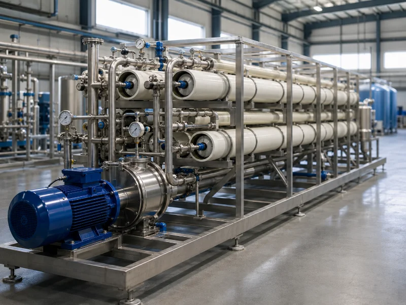
Brackish water RO design reconciles four constraints: required permeate flow and quality, feed water chemistry across its seasonal range, the hydraulic limits of the membrane elements, and the concentrate route the site can permit. Recovery sits where those constraints intersect, bounded by scaling saturation and minimum crossflow, while the production target sets membrane area and vessel count. Recovery is therefore an output of the analysis rather than a number chosen at the start. Where the ceiling lands depends on the individual scaling ions in the feed, the seasonal temperature range, and the concentrate volume the site can lawfully discharge.
Feed Water Data That Fixes the Design Envelope
Feed characterization for a brackish system needs more than bulk TDS, because the design envelope is set by individual scaling ions, the fouling load, and the temperature range the plant will see across a year. TDS tells you roughly what pressure the pump has to make. It tells you almost nothing about where recovery has to stop.
The ions that decide that stopping point are calcium, barium, strontium, sulfate, silica, and alkalinity, with iron, manganese, and organic carbon on the fouling side. Barium and strontium matter out of proportion to their concentration, because their sulfates are poorly soluble and can cap recovery at levels invisible in a TDS figure. A projection also needs the major background ions: sodium, potassium, chloride, and bicarbonate. Osmotic pressure and permeate quality are computed from the full composition, and a cation–anion charge balance is the standard check that the laboratory report holds together.
ASTM D4195, the standard guide for water analysis for reverse osmosis and nanofiltration application, sets out which analyses a membrane projection requires. An analysis that reports hardness and TDS but omits barium and silica cannot support a recovery decision, and the projection run from it will look clean.
Temperature carries two opposite constraints, and each needs its own design case. The minimum feed temperature commonly governs the highest required operating pressure, since water permeability falls as viscosity rises. The maximum temperature commonly produces the highest salt passage, and with it the worst permeate conductivity.
A design verified only at the annual average can miss both limits at once, so the projection should be run at the coldest and warmest cases, with RO high-pressure pump and motor sizing checked against the full operating envelope. Extra pump head answers the cold case and does nothing for the warm one, which is answered by element selection, a second pass, or blending capacity.
Silt density index covers the fouling side. ASTM D4189-23 defines it as a test method for waters of relatively low turbidity, such as well water and filtered water, and the standard itself notes that SDI varies with water temperature and with the manufacturer of the test filter. It is also not applicable to RO or UF permeate, which rules out a figure taken downstream of an existing membrane system. Two numbers measured under different conditions are not the same measurement, so we verify the test conditions behind an SDI value before treating it as a pretreatment specification.
Why the Highest Achievable Recovery Is the Wrong Design Target
Recovery on a brackish system is bounded by saturation limits in the concentrate, so the correct target depends on feed chemistry and the disposal route more than on how much water the plant would prefer to keep. At high salt rejection, the bulk concentration factor can be approximated as 1/(1 − Y), where Y is system recovery. Exact concentrate composition comes from the salt mass balance and the projected passage of each ion; ASTM D4692-01(2026) covers the calculation and adjustment of sulfate scaling potential for calcium, strontium, and barium sulfate in RO and NF concentrate.
Worked through, the arithmetic looks harmless. A feed of 100 m³/h at 75% recovery gives 75 m³/h of permeate, 25 m³/h of concentrate, and an approximate concentration factor of 4.0. What specifications tend to miss is that the factor is not linear in recovery: 60 to 70 percent raises it from about 2.5 to 3.3, while 75 to 85 percent raises it from about 4.0 to 6.7. The same ten-point step near the top of the range concentrates the tail elements roughly three times as hard as the equivalent step near the bottom.
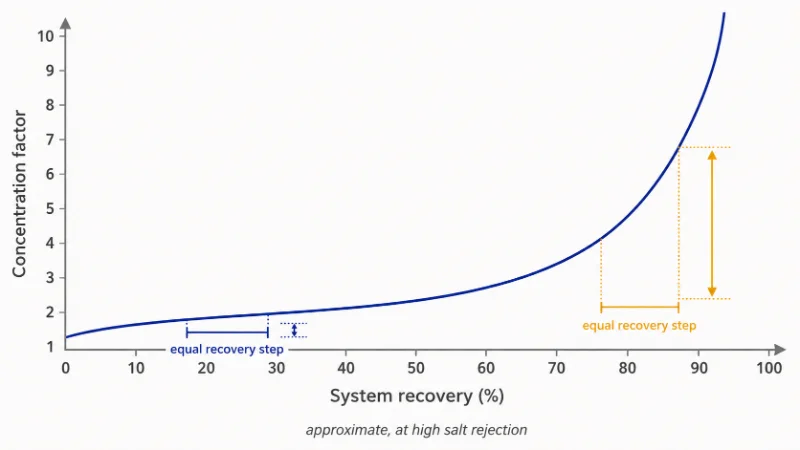
That is why a late, minor-looking increase in recovery is so often the one that pushes sulfate or silica past the envelope the antiscalant was selected to hold, and why a dose specified at one recovery cannot be carried over when the number is nudged up at commissioning. When a recovery target is set from a single feed sample instead of a seasonal range, the failure mode is familiar: tail-element scaling appears in the dry season, and the correction is either running below nameplate or raising cleaning frequency until the elements age out early.
The disposal route caps recovery from the other side. A discharge consent, an injection zone’s acceptance criteria, or the area of an evaporation pond fixes a maximum concentrate volume or strength, and that constraint comes from the site and the permit. Establish which of the two ceilings is lower before sizing anything.
There is also a case for not building an RO train at all. If the feed sits at the low end of the band and the real objection is hardness rather than dissolved salt, softening or nanofiltration will usually meet the specification at lower capital and running cost. RO earns its place when the salt itself has to leave the water, or when a conductivity ceiling makes partial removal insufficient.
Staging, Flux, and Element Count in Brackish Water RO Design
Array staging in brackish water RO design follows from the recovery target, because system recovery is produced by placing elements in series and every element carries a published limit on how much of its own feed it may convert.
One term pair is worth fixing before the table, since supplier pages blur it constantly. A stage is a group of pressure vessels at the same position in the concentrate path, so the concentrate of stage one becomes the feed to stage two. A pass is a complete RO step in which permeate from the first system becomes feed to a second. A two-stage single-pass system raises recovery; a double-pass system raises permeate purity, and the two are priced differently.
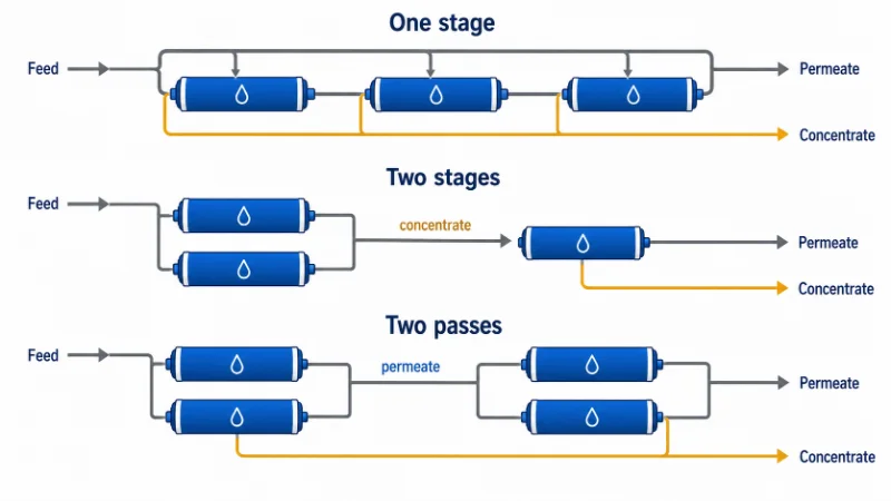
Most brackish reverse osmosis systems settle into one of three array patterns, and the choice among them is a recovery decision before it is a hardware decision.
| Configuration | Indicative recovery range* | What to check in the projection |
|---|---|---|
| One stage, vessels in parallel | ~40–60% | Maximum element recovery, lead-element flux, concentrate flow per vessel at minimum temperature |
| Two stages | ~70–80% | Staging ratio, tail-element recovery and flux against the element datasheet, stage pressure drop |
| Three stages | ~85–90% | Minimum tail concentrate flow, lead-to-tail flux balance, saturation limits, concentrate volume and disposal |
*Indicative values for conventional plug-flow systems using six-element pressure vessels, consistent with the staging and per-element limits set out in AWWA Manual M46, Reverse Osmosis and Nanofiltration and summarized for general RO practice in Water Conditioning & Purification. Vessel length, feed quality, and concentrate recycle all shift these bands, and the selected membrane manufacturer’s current design guidelines and projection software govern the final configuration. Flux-balancing measures such as interstage boosting, first-stage permeate back-pressure, or hybrid element selection are options the projection may justify, not defaults attached to any stage count.
If a revised proposal raises recovery without changing the array, the question is where the original hydraulic and scaling margin is being consumed. Re-run the projection and check maximum element recovery, minimum tail concentrate flow, maximum first-stage feed flow, flux balance, pressure drop, permeate quality, and saturation indices. A higher number may sit well inside the original design margin. It should never be accepted from the system-level percentage alone.
Design flux decides how many elements the recovery target is spread across. Higher flux buys fewer vessels and lower capital cost, and pays for it in fouling rate and cleaning frequency, since the same permeate volume is drawn through less membrane area. Feed quality decides where in the range flux belongs, which is why membrane manufacturers publish flux ranges by feed source: a stable well with low SDI supports a higher figure than a surface source with seasonal turbidity.
Pretreatment Targets the Design Depends On
Pretreatment scope on a brackish source is defined by the design assumptions it exists to protect: an SDI target at the membrane inlet, iron and manganese held below the level at which they oxidize onto the element, and residual free chlorine removed ahead of polyamide membrane. SDI of 5 is a commonly used maximum feed guideline, though the working target should come from the membrane manufacturer’s feed-source-specific limits, and cleaner well or membrane-filtered feeds are commonly designed around lower values. Allowable oxidant exposure belongs to the selected element’s datasheet as well.
Hardness control may use a water softener system, pH adjustment, antiscalant dosing, or a project-specific combination of these. The scheme comes out of the projected saturation limits at design recovery, the residual hardness after any softening step, chemical compatibility, and the operating margin the owner wants to hold.
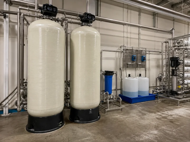
On wells with variable drawdown or blended aquifer zones, iron and manganese are worth re-testing under representative pumping conditions, since one commissioning sample rarely defines the annual envelope. Iron fouling announces itself as a rising pressure drop, not as a conductivity change, which is part of why it tends to be found late. Sizing inside that scope (media filter dimensions, backwash rates, UF flux) is driven by particulate load rather than salt chemistry, and it belongs after the recovery decision.
How to Check a Design Projection Before You Sign
A design projection is a model output, and its value depends on the analysis it was run from and the assumptions entered for aging, temperature, and flow. We compare the ion analysis behind a projection against what the site sampled, charge balance included, because a projection built on a partial analysis will look clean and still fail at the tail.
The feedwater envelope and the concentrate route belong at the front of the sequence. Both are commitments a project cannot cheaply unwind: piping, an injection well, or a pond is a capital and permit decision, and the chemistry ceiling moves everything downstream of it.
Membrane selection, materials, pressure ratings, instrumentation, control philosophy, and CIP provisions all have to be resolved before fabrication. Some membrane operating set points can be adjusted after start-up. Most mechanical and instrumentation decisions cannot be changed economically once the skid is built.
Four questions do most of the work on a projection you have been handed. Which feed temperature was used, and can the same case be run at the annual minimum and maximum? What fouling factor and annual salt passage increase were assumed, given that a projection at zero aging describes the first day only? What are the saturation indices at design recovery for every sparingly soluble salt present, not only for calcium carbonate? And how will performance be normalized once the plant runs?
ASTM D4516-19a, the standard practice for standardizing reverse osmosis performance data, sets out how to convert operating data back to fixed reference conditions, and it is applied stage by stage where the system is brine staged. Agreeing on that method before start-up is what makes a later performance dispute resolvable, because raw flow and conductivity readings drift with temperature and pressure on their own.
A projection settles the membrane envelope and nothing beyond it. Interconnecting piping, skid hydraulics, and the CIP membrane cleaning system are sized against site layout and cleaning chemistry, and they belong to a separate review.
The Data That Lets a Supplier Run a Real Projection
Of everything a brackish water RO design has to settle, the feed envelope and the concentrate route deserve confirmation first, because the recovery ceiling that follows from them fixes the array, the antiscalant program, and the concentrate volume in a single move. Permeate flow and permeate quality still define what the plant is for, and they set membrane area and vessel count once that ceiling is known.
Where a design has drifted in service, the tail of the last stage is usually the first place worth looking, since it runs at the highest concentration and the lowest crossflow in the system and registers a bad assumption earlier than the permeate meter does. We align a configuration to a site only once the seasonal analysis is in hand, and run the projection at the coldest and warmest cases.
A projection can be run the day the following exists. Without the first two items, anything a supplier produces is a template with your flow rate typed into it.
- A laboratory ion analysis with a cation–anion charge balance: calcium, magnesium, sodium, potassium, barium, strontium, iron, manganese; chloride, sulfate, bicarbonate, nitrate, fluoride; plus silica, TOC, pH, and conductivity, with sampling date and method
- Minimum and maximum feed temperature across a year, plus the wet and dry season TDS range if the source is a well
- SDI at the proposed RO inlet with its test temperature and filter type, or turbidity where SDI has not been run
- Target permeate conductivity or TDS, and whether that figure is a continuous limit or an average
- Required permeate flow together with operating hours per day, since a plant running eight hours is a different machine from one running around the clock
- The concentrate route, with any discharge limit or injection acceptance criteria attached to it
- Site constraints that fix the array: available footprint, clearance for element loading, and power supply
FAQ
No. Where hardness, sulfate, and silica all stay below their saturation limits at the design recovery, a system can run without one.
Usually only within the margin the original array was built with. Past that, concentrate flow per vessel falls below the minimum crossflow the element requires, and the practical options become adding a stage, adding recycle, or revising the antiscalant program, each confirmed by re-running the projection.
Sampling frequency follows source variability, permit requirements, and the cost of being wrong. A seasonal well may justify several full ion panels through the first operating year; a stable municipal feed can run on a smaller routine panel with periodic full verification.
Surface water changes the fouling side of the design far more than the salt side. Turbidity, organics, and biological activity vary week to week, which may justify ultrafiltration systems or a more robust conventional clarification and filtration train, and generally pushes design flux down. The recovery ceiling still comes from the same saturation arithmetic.
Only when the permeate conductivity target cannot be met in a single pass at the feed TDS involved. That is common for boiler feed and electronics-grade water, and uncommon for general process or potable supply.
Related Posts
- What Is Brackish Water Reverse Osmosis? — the process itself, for readers arriving before the design stage
- What Is the Best Filter for Brackish Water? — where RO sits against the other options for a saline source
- How Much Water Do RO Systems Waste? — the recovery question from the other side: how much of the feed leaves as concentrate
- Industrial Reverse Osmosis System Price — what the design decisions above cost, and how to compare quotes
- Industrial RO System Maintenance — daily checks and CIP triggers once the design is running