Installing a commercial or industrial reverse osmosis (RO) system is an engineering commissioning task, not a plumbing job. That difference decides whether the membranes reach their expected service life.
Every system is also built for one end use. A skid for process water, beverage production, potable water, or a healthcare application is designed and commissioned against the rules for that use. The sanitary, pharmaceutical, dialysis, and municipal-approval rules those uses carry sit outside a general installation guide.
This guide covers general commercial and industrial RO installation and commissioning. It walks through the work in the order a real project follows: the feed water and site first, then pretreatment, installation, safety checks, and startup.
What Sets Commercial and Industrial RO Installation Apart
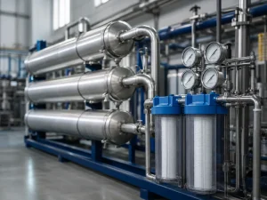
Commercial and industrial RO installation differs from a point-of-use setup in scale, construction standard, and the site work needed before the unit arrives. A residential filter sits under a sink. It runs on household pressure and installs with hand tools. A commercial or industrial system is another thing entirely. It is skid-mounted, produces hundreds to thousands of gallons a day, and needs dedicated pretreatment, a matched power supply, and floor space with room to service the membranes.
Many industrial RO trains run continuously, while smaller commercial systems cycle with tank level or demand. On a high-duty system, a weak feed line or a marginal power supply causes problems a household filter would shrug off — lost production, or nuisance shutdowns in the first shift. So both are checked before installation, against the skid’s rated flow and its nameplate voltage, phase, and frequency.
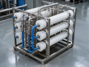
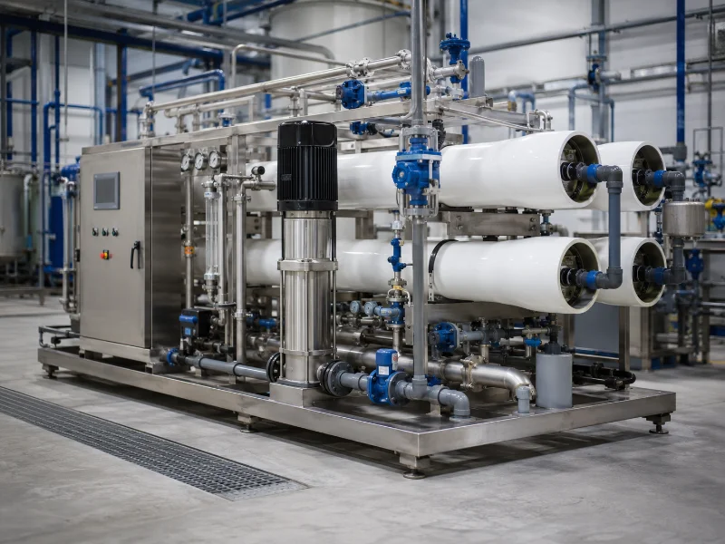
We build these systems as pre-assembled skids and pressure-test the piping and connections in our workshop before they ship. On site, the work is mostly the feed, drainage, and power connections, not building the unit.
Why Early RO Problems Usually Start Before Startup
Premature drops in RO flow or rejection usually trace back to the feed water and pretreatment, not to a fault in the membrane itself. Free chlorine that reaches a polyamide membrane oxidizes it. Hardness that slips past an exhausted softener scales it, and a heavy particulate load fouls the surface and raises differential pressure. Startup itself can cause damage too. Water hammer, too fast a pressure ramp, or a recovery set above the design value can harm the elements and housings during commissioning.
In the projects we review, the feed water report is often the part that is incomplete. That is why we check the source water against the membrane’s tolerance limits before we confirm a configuration. When a system is commissioned on water that was never fully analyzed, the membranes are usually the first part to show it. What looks like early failure — and many other reverse osmosis system problems — normally traces to a gap that was there from day one.
Feed Water and Site Data to Confirm Before Installation
Feed water analysis and site utilities set the pretreatment, pressure, and footprint an RO installation needs. Confirm both before you order equipment. A complete analysis reports far more than a single hardness figure. It should cover:
- pH, TDS or conductivity, and alkalinity
- calcium, magnesium, sulfate, and barium and strontium (the scaling indicators)
- soluble and colloidal silica, iron, and manganese
- free and total chlorine — chloramine behaves differently from free chlorine
- turbidity, SDI15, and organic load
- minimum, normal, and maximum feed temperature, with any seasonal swing
There is no single “maximum hardness” or “maximum silica” for every system. Those limits shift with recovery, pH, concentrate-side saturation, and the antiscalant you choose. Each parameter maps to a specific installation response.
| Feedwater issue | Why it matters at installation | Typical response | Parameter to verify |
|---|---|---|---|
| Free chlorine or chloramine | Oxidizes polyamide membranes | Carbon filtration or chemical reduction | Residual oxidant or ORP at the RO inlet |
| Scaling potential (hardness, silica, Ba/Sr) | Reduces flux and raises differential pressure | Softening, pH control, or antiscalant dosing | Concentrate-side saturation calculation |
| High particulate load | Fouls membranes and raises ΔP | Media, UF, or cartridge filtration | Turbidity and SDI15 |
| Iron or manganese | Forms deposits that resist standard cleaning | Feed-specific pretreatment set by the analysis | Dissolved vs. total metal in the analysis |
| Low feed temperature | Lowers permeate output at the same pressure | Size for the coldest expected condition | Minimum feed temperature on record |
The analysis sets the exact pretreatment train and the final membrane count for each project. So this guide assumes the RO system components and pretreatment are already matched to your water through engineering review, not picked from a generic spec sheet.
Site readiness matters as much as the water. The system needs a stable, level foundation and clearance above the pressure vessels to pull the membranes. It also needs a feed supply at the rated flow and pressure, drainage for the reject stream, and power at the right voltage, phase, and frequency. Keep the skid inside the environmental limits on its specification. A standard indoor skid needs protection from freezing, weather, heat, dust, and corrosive air. An outdoor or containerized system needs a rated enclosure and its own environmental controls. We check each feed water report against the destination market’s electrical and drinking-water rules, because a setup that fits one site’s power and chemistry may not fit another.
Matching Pretreatment to Your Source Water
Pretreatment protects RO membranes from the scaling, fouling, and chemical damage in source water. The stages you need depend on what the feed water analysis shows. A typical train removes bulk solids, controls oxidation or chlorine, manages hardness or scale, and ends with cartridge filtration. The order is not fixed. It depends on the source type, chemical compatibility, microbial risk, and the membrane maker’s requirements. Some polymers and negatively charged antiscalants can co-precipitate, for example, so dosing points and mixing have to match the design.
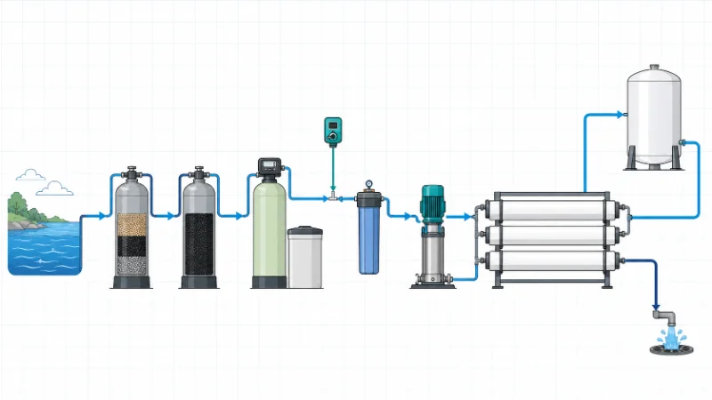
Cutting pretreatment to save on capital usually just moves the cost to the membrane budget. Fouled or scaled elements then get cleaned and replaced far more often. Overbuilding it adds footprint and maintenance the water does not need. We size the pretreatment equipment around your measured source water, not around a fixed package.
A water softener that is undersized, or behind on regeneration, lets hardness through and scales the membrane. So the softener is sized against the measured hardness and flow, not a nominal figure. Exhausted carbon lets chlorine reach the membrane. A carbon bed can also grow bacteria, and chloramine is not removed the same way as free chlorine. A sodium metabisulfite dosing system has to be guarded against overdosing, aging solution, and dosing failure.
Safety and Code Checks Before Energizing the Skid
Before the RO skid is energized, it has to clear a set of electrical, pressure, and chemical safety checks. Qualified personnel sign these off, separate from the process steps above. At a minimum:
- Qualified personnel complete and verify all electrical work, to the code in force at the site — for example NFPA 70 in the US, or IEC 60204-1 on export machinery. The control panel is built to the standard that applies, such as UL 508A where required.
- Isolate and verify all energy sources before any servicing, under the lockout/tagout rule in force — OSHA 29 CFR 1910.147 in US facilities, or the local equivalent.
- Confirm pump rotation before running at full load.
- Verify the pressure-relief, low-pressure or low-feed shutdown, and dosing-failure interlocks.
- Depressurize the vessels and piping before opening any housing or end cap.
- Review the chemical SDS requirements, and have PPE in place for antiscalant, acid, alkali, and dechlorination chemicals.
- Confirm drainage, backflow protection, and any required air gap under local plumbing rules.
None of this replaces the approved P&ID, the electrical drawings, or the membrane maker’s startup procedure. These are the minimum confirmations before high-pressure operation begins.
The Installation Sequence for a Skid-Mounted System
The installation sequence for a skid-mounted RO system runs from site preparation to electrical tie-in. Following it in order keeps a step done out of turn from compromising commissioning. Once the site and feed conditions are confirmed, the physical work moves through a predictable set of stages.
- Prepare and level the foundation, and confirm the environmental limits and the clearance above the vessels for membrane removal.
- Set and secure the skid, keeping service access to the pump, membrane vessels, and control panel.
- Install and tie in the pretreatment stages upstream of the RO feed.
- Connect the inlet, product, and reject lines with corrosion-resistant piping. Support the piping on its own, so its weight does not stress the skid nozzles. Add isolation valves, sampling points, and drain, flush, or CIP connections.
- Complete the electrical connections and instrumentation to the control panel, to code and to the rated voltage, phase, and frequency.
- Add post-treatment and storage — UV, pH correction, a storage or repressurization tank — as the application needs, then leave the unit ready for flushing.
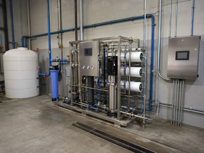
The skid’s piping and connections are pressure-tested in our workshop before shipment, so on-site work centers on the field connections, not on building the unit. Even so, every field connection is leak-checked before power is applied. A skid set without clearance above the membrane pressure vessels will still commission. But the first membrane change becomes hard, so check vertical space against the vessel length, not just the skid footprint.
Commissioning, Startup, and Acceptance Data
Commissioning confirms that an installed RO system meets its design pressure, flow, and permeate-quality targets before it goes into production. The startup readings then become the baseline for monitoring. New membranes and filters carry preservatives and carbon fines. Flush these out first, by the manufacturer’s procedure, before any product water is used.
Startup follows a controlled sequence. Do not switch straight to the high-pressure pump. Inspect the system first and confirm the concentrate control valve is open. Flush the pretreatment on its own, then purge air from the vessels at low pressure and low flow. Raise feed pressure slowly, to avoid water hammer and shock to the elements and housings. Bring recovery up to the design value in steps, never above it, and send the first permeate to drain. For the pressure-ramp rate and the flush volumes, follow the membrane maker’s limits, not a single universal figure.
Acceptance readings cover a standard set of values:
- feed, permeate, and concentrate flow — for the mass balance and recovery
- feed, interstage, and concentrate pressure — with the differential pressure across each stage
- feed and permeate conductivity, plus temperature and feed pH
- a chlorine or ORP check, to confirm dechlorination
- an SDI or turbidity check, to confirm particulate control
Two simple ratios help with field trend-checking:
- Recovery (%) = permeate flow ÷ feed flow × 100
- Salt rejection (%) = (1 − permeate conductivity ÷ feed conductivity) × 100
These simple ratios are for field trends only. Formal acceptance follows the membrane maker’s method and design software, with temperature correction applied. Over time, the readings that matter most are the normalized permeate flow, the normalized salt passage, and the stage differential pressures. Normalization separates a real change in the membrane from a change in temperature, pressure, or feed salinity. Log only raw permeate conductivity, and a temperature swing can look like fouling. After 24 to 48 hours of running, review the system again — pressure, ΔP, flow, temperature, recovery, and conductivity — before it goes to automatic operation.
We record the startup readings as the operator’s reference point, taken from the panel gauges and water quality instruments. In the first weeks, track the normalized flow and salt passage, and confirm the softener is regenerating and the carbon is not exhausted. That catches problems while they are still small. The service interval for filters and membranes then comes from this baseline and the duty cycle, not from a calendar alone.
Getting the Installation Right From the Start
A good RO installation is mostly decided before the first connection. Three things carry it: the feed water the system will run on, the pretreatment that protects it, and the acceptance criteria that prove it works. Settle those, and the physical installation is largely routine field work.
We design and fabricate these systems as pre-assembled, pressure-tested skids. Before we confirm a configuration, we review each project’s source water and site electrical standards. The pretreatment train and the final sizing depend on conditions only a project-specific analysis reveals. The workshop pressure test settles what we can verify before shipment. The feed water, drainage, and power at your site are confirmed on the ground, along with commissioning by qualified personnel to the approved drawings and the membrane maker’s procedure.
The best next step is to send us what we need to confirm a configuration, especially for an industrial RO water system on a new site:
- the latest feed water analysis
- the required permeate flow and daily operating hours
- the product-water specification
- the source-water temperature range
- the available electrical supply
- the installation environment and destination market
Our engineering team will match the equipment and pretreatment to those conditions.
FAQ
Installation time depends more on how ready the site is than on the system itself. A pre-assembled skid connects quickly. The slow parts are usually the site utilities and the pretreatment. Getting the feed, drainage, and power in place, and commissioning the pretreatment, takes longer than bolting up the skid. It helps to plan the work in phases: site prep, setting the skid, piping and electrical, pretreatment commissioning, membrane startup, and performance verification. Most delays come from utilities that are not ready when the equipment arrives.
Your site team can usually handle the mechanical connections, but the electrical work and startup should be done by, or with, qualified personnel. Setting the skid and running the feed, drain, and product piping is normal work for a competent contractor. Wiring to code, confirming pump rotation, checking the interlocks, and the first high-pressure run are where mistakes get expensive. We supply the drawings and the startup procedure, and we can support commissioning so the first run follows the membrane maker’s limits.
The difference is mainly scale, duty, and construction standard. A commercial system serves lighter-duty sites — a restaurant, a hotel, a small plant — at lower volumes, and it often cycles on and off with demand. An industrial system runs higher volumes, is built for continuous duty, and is made to a higher construction standard, with heavier vessels and more redundancy for critical processes. Both are installed and commissioned the same way. The pretreatment, piping, and electrical work simply scale up with the system.
Most systems need one, because the RO makes water at a steady rate while the site draws it in bursts. A storage tank buffers that gap, and a repressurization pump then delivers the stored water at the pressure the site needs. Whether you need one, and how big, depends on your peak demand and how much treated water you want on hand. That is settled during design, alongside the recovery target and the pretreatment.
Recovery is the share of feed water that becomes permeate, and commercial systems commonly run around 50 to 75 percent. The right figure for your water is not fixed. Pushing recovery higher cuts wastewater, but it raises the risk of scaling and shortens membrane life. So it is set from your feed water and scaling potential during design, then dialed in at commissioning.