
Multi Media Filters
Industrial Multi Media Filter Systems for RO Pretreatment and High-Purity Water. A multi media filter is the standard first-stage solids removal step in industrial RO pretreatment, boiler feedwater conditioning, and high-purity process water systems. As a media filtration system, three stratified layers capture suspended solids progressively across the bed depth, protecting downstream membranes, boilers, and ion exchange resin from premature fouling.
Where Multi-Media Filtration Fits in Your Pretreatment Chain
A multi media filter handles the bulk suspended-solids load before more sensitive downstream equipment sees the water. In a standard industrial RO pretreatment sequence, the treatment train reads: Source Water → Multi-Media Filter → activated carbon filter → cartridge filter housing → RO high-pressure pump → RO membrane array.
Bulk Solids Removal
The multi-media filter removes turbidity, silt, rust, sediment, and organic debris — particles in the 5–20 micron range — so the activated carbon stage downstream is not prematurely consumed by particulate loading.
Carbon and Cartridge Protection
The cartridge filter at the final polishing stage provides last-line RO membrane protection. Running the sequence without a multi-media filter shifts the entire particulate load onto the carbon and cartridge stages, shortening their service life disproportionately.
Underperforming Systems
If your cartridge filters are blinding too quickly, the upstream bulk filtration stage in the pretreatment filtration train is likely undersized, misconfigured, or absent. This is the first variable we evaluate when reviewing an existing system.
Depth Filtration Across a Stratified Multi-Layer Media Bed
Multi media filters achieve their removal performance through depth filtration across a stratified media bed — a media filtration system design that captures suspended solids progressively at multiple depths rather than at one surface.
Depth Filtration vs Surface Filtration
In surface filtration, contamination accumulates on the outer element face and pressure drop rises steeply as the surface clogs. In a media filtration system, water passes downward through a graded bed where particles are captured at multiple levels throughout the media stack — reaching typical suspended-solids reduction in the 5–20 micron range and running substantially longer between backwash cycles.
Density-Based Stratification
Stratification is maintained by the density difference between media types. Anthracite has a specific gravity of approximately 1.5; silica sand approximately 2.65; garnet approximately 4.0. During backwash, each layer re-stratifies to its original position because heavier media settles faster — this self-sorting behavior is what allows depth filtration to run longer between cycles than a single-media sand filter.
Three-Media Bed with Support Gravel Layer
| Layer | Media | Particle Size | Specific Gravity | Primary Function |
|---|---|---|---|---|
| Top | Anthracite | 1.0–2.0 mm | ~1.5 | Coarse pre-screening; captures large particles and organic debris; longest void channels |
| Middle | Silica Sand | 0.5–1.2 mm | ~2.65 | Intermediate retention; captures mid-range particles; bridges anthracite and garnet |
| Bottom | Garnet | 0.3–0.5 mm | ~4.0 | Fine polishing; captures fine silt and colloidal particles before the underdrain |
| Sub-base | Support Gravel | 6–20 mm | ~2.6 | Supports the media bed; protects the underdrain from fine media migration |
The engineering consequence of inverting this order — placing garnet above anthracite, for example — is that fines from the denser lower media migrate upward into coarser channels during operation, collapsing bed structure and degrading run time. This is the most common media installation error we encounter when reviewing systems that are underperforming relative to their design specification.
Depth Filtration vs. Single-Media Sand: The Performance Gap
When source water conditions or downstream equipment demand more than a quartz sand filter can reliably deliver, we specify a multi-media filter. The differences are quantifiable across every performance axis that matters for RO pretreatment.
| Performance Metric | Multi-Media Filter | Single-Media Sand Filter |
|---|---|---|
| Filtration accuracy | Typical suspended-solids reduction range: approximately 5–20 microns under confirmed media configuration, loading rate, and influent conditions. Not equivalent to an absolute cartridge-filter micron rating | 20–50 microns |
| Surface loading rate | 5–15 m/hr; up to 10 gpm/ft² for industrial loading. Higher loading rates reviewed only when influent turbidity, SDI target, and backwash capacity support the selection. | 5–8 m/hr; limited by single-bed compaction |
| Run time between backwash cycles | Longer filter runs than comparable single-media sand filters are expected when media grading and backwash design are correct | Baseline |
| Turbidity reduction | Project-specific; strongly dependent on influent turbidity, coagulant use, loading rate, and backwash condition | 60–80% |
| SDI suitability for RO inlet protection | Designed to support SDI <5 targets; review required for high-turbidity feeds. Final RO inlet protection still requires downstream cartridge filtration; SDI performance is confirmed by site testing, not by MMF vessel selection alone. | Marginal; often insufficient as a standalone RO pretreatment step |
| Backwash water consumption per unit of volume filtered | Lower (longer run times, fewer cycles) | Higher |
We specify a multi media filter over a single-media sand filter when inlet turbidity exceeds approximately 5 NTU and the downstream equipment includes an RO system, ion exchange resin, or boiler feedwater circuit that requires membrane or resin protection. For source waters consistently below 1–2 NTU with no SDI requirement, a single-media sand filter may be sufficient — but any project involving RO pretreatment should be evaluated against the SDI <5 design target, not inlet turbidity alone.
When upstream coagulant addition — alum, ferric sulfate, or polymer — is included in the pretreatment design, the effective filtration threshold drops to 5–10 microns and SDI reduction improves accordingly. We evaluate the coagulant-addition decision based on source water characterization, target SDI, and operating chemistry. It is not a default addition; it changes the backwash chemistry, drain loading, and media fouling characteristics.
What Multi-Media Filtration Handles — and What It Does Not
A multi-media filter handles the bulk suspended-solids load — it does not remove dissolved contaminants, and specifying it to do so produces a system that cannot meet water quality targets regardless of vessel configuration.
What a Multi-Media Filter Removes
- Suspended solids and turbidity (5–20 microns)
- Silt, rust, and sediment
- Coagulated organic debris
- Source water with coagulant addition: down to 5–10 microns
What Requires Downstream Equipment
- Dissolved salts / TDS → RO or ion exchange downstream
- Hardness (calcium, magnesium) → softener or antiscalant dosing
- Residual chlorine and dissolved organics → carbon filtration downstream
- Fine colloids below 1 micron → UF or cartridge polishing
- Dissolved heavy metals at trace concentrations → IX or adsorption media
Understanding this boundary prevents two common engineering errors: over-specifying multi-media filtration to solve a dissolved-contaminant problem it cannot address, and under-specifying by expecting it to deliver finished water quality without downstream polishing.
When we receive an inquiry that asks for turbidity removal and TDS reduction in a single vessel, we clarify this boundary during the first technical exchange — specifying a downstream softener, carbon filter, or RO stage is not additional scope, it is preventing a system that cannot meet water quality specifications regardless of how the media filter itself is configured.
Technical Operating Parameters
The operating envelope for a Hiju multi media filter vessel spans surface loading from 5 to 15 m/hr, typical suspended-solids reduction in the 5–20 micron range depending on media configuration and upstream coagulant addition, and vessel operating pressure up to 10.3 bar (150 psi) for FRP — with higher pressure ratings available in carbon steel or stainless steel construction.
| Parameter | Range / Options |
|---|---|
| Filtration accuracy | Typical suspended-solids reduction range: approximately 5–20 microns (design-dependent); 5–10 microns with upstream coagulant addition. Not equivalent to an absolute cartridge-filter micron rating. |
| Surface loading rate | 5–15 m/hr; 5 gpm/ft² optimal for RO pretreatment; up to 10 gpm/ft² for industrial loading. Higher loading rates reviewed only when influent turbidity, SDI target, and backwash capacity support the selection. |
| Backwash flow rate | Common design review range: 12–15 gpm/ft² of vessel cross-sectional area; final value confirmed by media type, particle size, water temperature, and underdrain design. Air scour option: 2–4 cfm/ft² |
| Backwash trigger options | Differential pressure 0.5–1.0 bar; time-clock; PLC-controlled sequencing |
| Backwash frequency | Every 24–72 hours; influent turbidity and loading rate dependent |
| SDI output target | Designed to support SDI <5 for RO inlet protection; subject to source-water and design review. Final RO inlet protection still requires downstream cartridge filtration; SDI performance is confirmed by site testing, not by MMF vessel selection alone. |
| Operating pressure | Up to 10.3 bar (150 psi) for FRP vessels; higher ratings for carbon steel and stainless steel |
| Operating temperature | Up to 50°C (120°F) for standard FRP; higher for carbon steel or stainless steel shell variants |
| Vessel diameter range | 200 mm (8″) to 2,400 mm (96″) custom. Large-diameter carbon steel or stainless vessels reviewed as engineered builds, not catalog defaults. |
| Vessel materials | FRP; carbon steel (epoxy-lined or coated); 304 or 316L stainless steel |
| Control valve type | Automatic (time-clock); pressure-differential actuated; PLC-controlled (project option) |
| Inlet/outlet connections | Flanged or threaded; project-specific |
| Certifications | CE and ISO 9001 standard; ASME-stamped vessel configurations available where specified |
Three Variables Confirmed by Engineering, Not Catalogue
Three configuration variables — vessel material, control valve type, and media specification — are each determined by feedwater chemistry, operating pressure, site automation level, and destination country compliance requirements; none defaults to a catalogue standard without engineering input.
Vessel Material Selection
FRP is standard for freshwater applications at pressures up to 10.3 bar (150 psi) and temperatures up to 50°C. For vessels above approximately 1,200 mm diameter or higher pressures, carbon steel with internal epoxy lining is specified.
For food, beverage, pharmaceutical-adjacent, or aggressive-water applications where material compatibility, hygiene documentation, or corrosion resistance is required, 304 or 316L stainless steel is available. Final suitability depends on the buyer’s process-water standard and validation requirements.
Control Valve Selection
Time-clock backwash controllers initiate on a fixed interval — appropriate for stable-loading applications. Pressure-differential-actuated valves trigger only when differential pressure reaches 0.5–1.0 bar, extending run times when inlet turbidity is lower than design loading.
PLC-controlled systems integrate backwash sequencing with the broader plant automation loop, including coagulant dosing and drain valve sequencing. Control approach is specified based on facility automation level and backwash water constraints.
Media Specification
Standard configuration is the three-layer anthracite / silica sand / garnet stack, suitable for most municipal, industrial, and RO pretreatment applications. A four-layer configuration adds support gravel between garnet and the underdrain assembly.
Media specification — including layer depth ratios, particle size distribution, and uniformity coefficient — is confirmed during the engineering phase. Loading rate, vessel diameter, and inlet water characterization all influence the media bed design.
Backwash Design: The Most Frequently Under-Specified Variable
Backwash design is the most common source of performance degradation in multi media filter systems, and the failure mode most frequently traced back to procurement rather than operation. A correctly designed backwash cycle re-fluidizes the media bed sufficiently to release trapped particles and maintains density-based stratification so each layer returns to its correct position after the backwash flow stops.
A common design review range for backwash flow rate in a multi-media bed is approximately 12–15 gpm/ft² of vessel cross-sectional area; the final value is confirmed by media type, particle size, water temperature, desired bed expansion, and underdrain design.
1,000 mm Vessel — Backwash Sizing Example
Cross-sectional area: 0.785 m² = 8.45 ft²
Backwash demand at 12–15 gpm/ft²: 23–29 m³/hr
Backwash supply pumps sized for service flow rather than backwash demand are the most common cause of bed under-expansion and progressive garnet migration.
Under-Sized Backwash Flow
When the backwash supply pump is sized for service flow rather than backwash demand, the bed does not fully expand. Trapped particles remain in the media voids and garnet fines migrate upward into the sand layer. After repeated cycles, this intermixing collapses the effective filtration gradient and raises baseline pressure drop permanently.
Backwash Water Quality
Backwashing with water containing elevated residual free chlorine can degrade anthracite media over time, particularly in warm-water installations. The acceptable chlorine ceiling depends on media grade and operating temperature; the backwash water source should be confirmed during engineering review.
Air Scour Option
Injecting compressed air at 2–4 cfm/ft² before or concurrent with the water backwash phase is specified for high-turbidity applications where biological growth or sticky organic matter creates media compaction that water backwash alone cannot release. The drain system and vessel internals must be rated for the additional turbulence.
Media Condition Assessment
Media service life is not evaluated on a fixed replacement schedule. Condition is assessed based on sustained pressure drop trends that backwash cannot correct, outlet water quality degradation over time, and evidence of media migration or compaction at scheduled maintenance visits.
Where Multi-Media Filters Are Specified
Industrial RO Pretreatment
SDI <5 target at MMF outlet protects the RO membrane array from particulate fouling that elevates normalized pressure drop and triggers premature cleaning cycles. For seawater and brackish water RO feedwater, coagulant dosing requirements and SDI targets are evaluated against source-water characterization provided during engineering review.
Boiler Feedwater Polishing
Power generation, process steam, and industrial heating circuits require feedwater turbidity below 1 NTU before the deaerator or direct boiler inlet. A multi-media filter at 5–7 m/hr surface loading with the three-layer configuration provides this level of solids removal for most surface water or municipal supply feedwater inputs, subject to inlet turbidity characterization.
Food and Beverage Water Pretreatment
Industrial beverage production, dairy processing, and food ingredient manufacturing require reliable suspended-solids removal before carbon filtration and RO polishing. Stainless steel vessel construction is available for food-grade applications where material traceability is a compliance requirement. Our food and beverage water treatment systems integrate multi-media filtration as the primary pretreatment stage.
Municipal Drinking Water Pretreatment
Water authorities treating surface water, river intake, or reservoir supply use multi-media filtration as a standard pre-clarification step before disinfection, softening, or membrane polishing. Vessel diameter and parallel filter train configuration are sized to daily volume demand, with backwash water recovery rates designed for the regulatory requirements of the municipal and community drinking water project location.
Cooling Tower Makeup Water
Industrial cooling circuits are sensitive to suspended solids and biological debris that promote biofouling, scale, and corrosion. Multi-media filtration of makeup water to below 5 NTU reduces the suspended-solids load entering the recirculating circuit, lowering biocide consumption and extending heat exchanger cleaning intervals.
Industrial Wastewater Polishing for Reuse
Where zero-liquid-discharge or water-reuse targets require pre-polishing of treated effluent before RO or regulated discharge, multi-media filtration provides TSS reduction to levels compatible with downstream membrane tolerance. Higher influent turbidity in this application requires detailed loading rate and backwash cycle design based on effluent characterization.
Manufacturing Quality and Export Certifications
2016
Established
70,500 m²
Total facility
21,000 m²
Dedicated workshop
28 / 78
Engineers / technicians
20+
Countries and regions
Available
OEM / ODM
Southeast Asia · Middle East · Africa · South America · Central Asia
In-House Capability
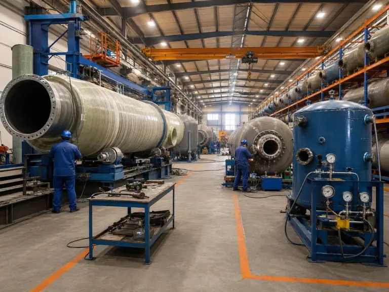
We design and manufacture multi-media filter systems from our facility covering 70,500 m² of total floor area with 21,000 m² of dedicated workshop space. Our team of 28 engineers and 78 technicians handles vessel design, media selection, control valve integration, and pre-delivery inspection in-house.
Export Documentation
Vessel pressure documentation, material certifications, and hydrostatic test records are standard deliverables for export projects. For destination countries with local inspection authority requirements beyond CE and ASME, we recommend confirming the regulatory path during the engineering review phase.