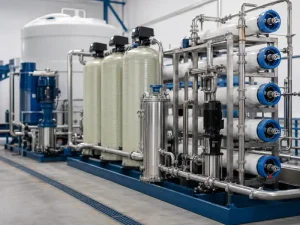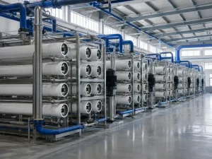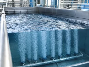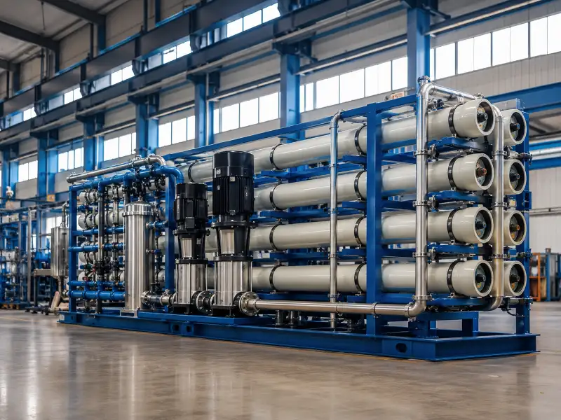
Membrane technology for water treatment is a family of pressure-driven processes — microfiltration, ultrafiltration, nanofiltration, and reverse osmosis — that remove contaminants by size or charge rather than by chemical dosing alone. Which process fits a project depends on three variables you must confirm before specifying any system: what is in the source water, what the treated water has to meet, and what recovery and energy budget the site can sustain. We design and fabricate these systems for industrial and municipal buyers. The recurring lesson is that the membrane is rarely the hard part. Matching it to verified water chemistry is.
This guide is for importers, distributors, EPC contractors, and procurement teams evaluating membrane options. It gives a decision framework, not a chemistry lecture. It covers how to choose between processes, not how to install a system or design the civil works upstream of the plant. Those depend on site conditions and belong in a project-level engineering review.
The Four Membrane Processes Ranked by Pore Size and What Each Removes
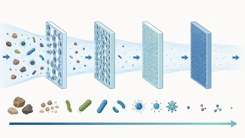
The four membrane processes separate on a spectrum of pore size. Each step down that spectrum removes more contaminants but demands more pressure and energy. Microfiltration sits at the coarse end and reverse osmosis at the fine end. The gap between them is where most specification mistakes happen. A tighter membrane than the application needs raises operating cost for no benefit. A looser one fails the water-quality target.
The practical distinctions come down to four variables: pore size, operating pressure, what the membrane rejects, and recovery rate. We check any candidate process against these before confirming a configuration. A membrane that rejects the target contaminant on paper can still be wrong if its recovery rate strands too much water as concentrate.
| Process | Pore size | Relative pressure | Primary removal target | Relative recovery |
|---|---|---|---|---|
| Microfiltration (MF) | 0.1–0.45 µm | Lowest | Suspended solids, turbidity, protozoa, bacteria | Highest |
| Ultrafiltration (UF) | 0.01–0.1 µm | Low | Above, plus colloids, macromolecules, some viruses | High |
| Nanofiltration (NF) | ~0.001–0.01 µm | Moderate–high | Above, plus hardness and divalent ions | Moderate |
| Reverse osmosis (RO) | <0.001 µm | Highest | Above, plus monovalent dissolved salts (TDS) | Lower |
The pore-size ranges above are well established. Exact pressure, recovery, and salt-rejection figures depend on feed-water salinity, temperature, membrane model, and target permeate quality. So we treat published numbers as starting points and confirm them against the project’s own water analysis, rather than quoting a single figure that may not hold on a given feed. The pattern itself stays the same: as pore size shrinks, rejection improves but recovery falls and energy demand climbs. The question is not which membrane is best. It is which membrane removes what this water requires without over-engineering the rest.
The Most Common Selection Mistake: Specifying RO When NF or UF Would Do
The most frequent error in membrane selection is defaulting to reverse osmosis when the target only needs a looser membrane. RO is the most capable process, which is exactly why buyers reach for it. But capability the application doesn’t need still gets paid for in pressure, energy, and replacement cost every operating hour. When a project does call for it, reverse osmosis systems earn that cost. The problem is reaching for them by default.
The usual trigger is mistaking a hardness or organics target for a dissolved-salt target. The result is an RO system running where nanofiltration would have met the spec at lower pressure, or a multi-stage train where ultrafiltration alone would have cleared the pathogen requirement. We see this most often when a target is written as “high purity” without naming the contaminants that define it. The fix is not a different membrane. It is a contaminant-by-contaminant target list confirmed before selection, because “purity” is not something a membrane can be matched against.
A second version runs the other way: choosing MF or UF for a feed that holds dissolved salts or hardness those membranes cannot touch. Microfiltration and ultrafiltration remove particles, microorganisms, and macromolecules, but they pass dissolved ions largely unchanged. If the source water carries a salinity or hardness load, no amount of MF or UF will reach a low-TDS target. That needs NF or RO downstream, and the looser membrane becomes pretreatment rather than the final barrier.
Virus removal is often overstated, so it is worth stating plainly. Ultrafiltration strongly removes suspended solids, bacteria, protozoa, and many viruses. But virus rejection depends on the membrane rating, integrity testing, and the log-removal target required. Where virus removal is a regulatory requirement, confirm it against the applicable standard. It may call for NF, RO, UV, or a separate disinfection step rather than UF alone. Microfiltration has larger pores. It removes protozoa and bacteria but should not be relied on for viruses at all.
How to Choose a Membrane Process From Your Source Water and Target
Membrane selection starts from two confirmed inputs — the source-water analysis and the treated-water target — and works inward to the process that bridges them at acceptable recovery. The source water sets what has to be removed and what will foul the membrane. The target sets how tightly the water must be polished. Neither can be assumed from the application name alone, because the same nominal application carries very different water chemistry depending on location.
The variables that drive the decision, in the order we review them:
- Dissolved salts and TDS — if the target means lowering total dissolved solids, the choice narrows to NF or RO; particle-removing membranes cannot help.
- Hardness (divalent ions) — nanofiltration rejects most divalent ions while passing some monovalent ones, which makes it a lower-pressure option for softening targets that do not need full desalination.
- Pathogens and turbidity — ultrafiltration systems give a strong barrier to protozoa, bacteria, and many viruses; microfiltration handles protozoa and bacteria but not viruses.
- Recovery and concentrate disposal — tighter membranes produce more concentrate, and where that stream goes affects both feasibility and operating cost.
Source water often varies by season or by intake. This is common with surface water and coastal sources, such as those feeding seawater desalination plants. When it does, the configuration has to be sized for the worst case, not the average. We review each inquiry against the actual source-water conditions, the destination-market requirements, and the site’s electrical supply before confirming anything. A system sized to an averaged analysis will underperform whenever the feed swings toward its dirty end.
What a Source Water Analysis Should Include Before Membrane Selection
A source-water analysis is the single input that most decides whether a membrane system performs, and it should be in hand before any process is chosen. Selecting a membrane without a current, representative water test is the most common reason a system that looked right on paper underperforms in the field. The analysis need not be exhaustive. It does need to cover the parameters that drive both process choice and pretreatment design.
The parameters we look for on an inquiry, before recommending a configuration:
- Total dissolved solids (TDS) and conductivity — sets whether NF or RO is needed at all.
- pH and temperature — affect membrane compatibility and achievable flux.
- Turbidity, suspended solids, and SDI (silt density index) — the fouling indicators that size pretreatment.
- Hardness and alkalinity — drive scaling risk and antiscalant strategy.
- Calcium, magnesium, sulfate, and silica — the specific scale-forming ions.
- Iron and manganese — foul membranes if not removed upstream.
- Free chlorine or ORP — polyamide membranes are chlorine-sensitive, so this dictates carbon pretreatment.
- TOC, COD, or BOD — organic load that affects fouling and process choice.
- Microbial indicators — biofouling risk.
- Target permeate limits and required recovery rate — the output side of the specification.
- Concentrate discharge route — a feasibility constraint, not an afterthought.
This list is also the fastest way to tell whether an inquiry is ready to specify. When most of these are unknown, the next step is testing, not membrane selection. Every figure below the membrane rating in a proposal is only as reliable as the water analysis behind it.
A Membrane Selection Matrix for Common Feed-Water Conditions
A selection matrix maps common feed-water conditions to a recommended process. It is the fastest way to sanity-check a direction before committing to a full engineering review. The matrix below shows how our engineering team narrows options on a first pass. It is a starting point for discussion, not a substitute for matching a real water analysis to a specific configuration.
| Feed-water condition | Main issue | Process direction | Why |
|---|---|---|---|
| High turbidity, low TDS | Particles, pathogens | UF or MF, plus disinfection | Salt removal not needed; avoid over-using RO |
| High hardness, moderate TDS | Scaling, hardness | NF | Rejects divalent ions at lower pressure than RO |
| High TDS or brackish water | Dissolved salts | RO | TDS reduction requires a dense membrane |
| Surface water, seasonal turbidity | Variable fouling load | UF plus pretreatment | Stabilizes feed before NF or RO |
| Industrial reuse with organics | COD, TOC, fouling | Pretreatment plus UF, NF, or RO | Final stage depends on the named target |
The matrix narrows the field. It does not close the decision. Two sites with the same headline condition can need different configurations once the actual ion balance, temperature, and recovery target are on the table. A high-TDS feed points to RO, but brackish water RO systems for two such sites can still differ once those details are confirmed. We treat the matrix as the first question, then confirm against the water analysis.
Why Pretreatment Decides Whether the Membrane Survives
Pretreatment decides membrane life far more than the membrane brand does, and it is the part of the train buyers most often underbudget. Every membrane process is vulnerable to fouling — the buildup of particles, scale, or biological growth on the membrane surface — and the finer the membrane, the more sensitive it is. A reverse osmosis system fed unprotected raw water does not fail gracefully. Flux declines, pressure climbs to compensate, and the membranes need cleaning or replacement well before their rated life.
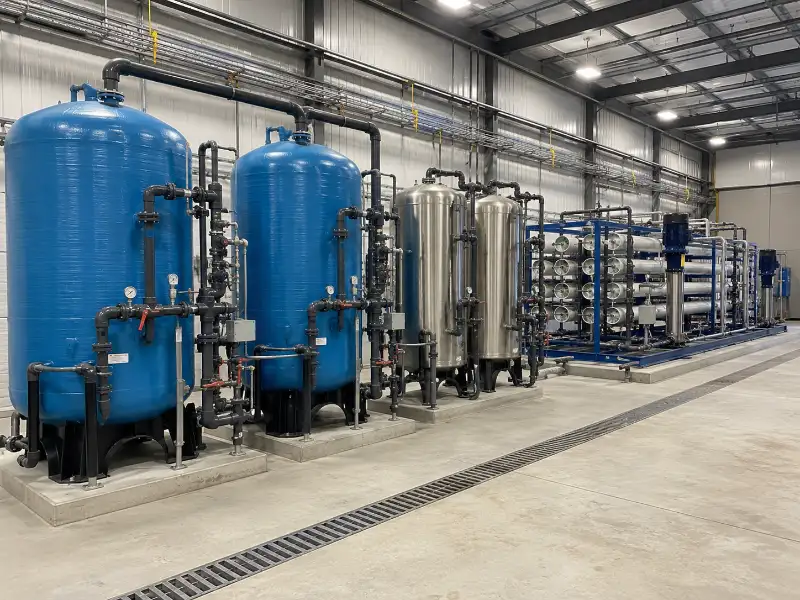
In our experience, the membrane elements are rarely the first thing to need attention on a poorly specified system. The pretreatment stage is. That is where an undersized filter or a missing antiscalant step shows up first. When a feed-water analysis is taken once and treated as fixed, the train gets sized for that snapshot. Then the first seasonal turbidity spike or hardness swing overwhelms a pretreatment stage that looked adequate on paper. The correction is to size pretreatment against the range the source water actually shows, not a single sample, and to verify the upstream barrier protects the membrane it feeds.
Typical pretreatment depends on the source, but the logic stays the same: remove what would foul the membrane before it reaches the membrane. That can mean multimedia or sand filtration for suspended solids, activated carbon for chlorine and organics ahead of polyamide RO membranes, cartridge filtration as a final guard, and antiscalant dosing where hardness would otherwise precipitate. UF often sits ahead of RO and NF because it gives a more consistent feed than conventional filtration, whatever the raw water does. Which combination applies depends on the water analysis. Getting that sequence right is the difference between a membrane that meets its rated life and one that does not.
How to Verify a Membrane System Before You Commit
A membrane system should be verified against named criteria before purchase, not assumed to perform from its datasheet. Datasheet rejection rates are measured under standard test conditions that rarely match a specific site. So the useful question is not what the membrane rejects in the lab. It is what this configuration will deliver on this feed water at the required recovery. That answer comes from matching the system to a real water analysis, not from a catalog figure.
The verification points we work through with buyers before confirming a build:
- Feed-water analysis — a current, representative source-water test covering the parameters listed earlier, ideally across the seasonal range.
- Permeate target — the specific contaminants and limits the treated water must meet, written as numbers rather than a quality label.
- Applicable standards — the destination market’s governing standards for the system type and end use, confirmed for the project rather than assumed, since the relevant standard depends on process, region, and application.
- Recovery and concentrate plan — the target recovery rate and a confirmed route for the concentrate stream.
- Site conditions — electrical standards, ambient and feed-water temperature, and footprint constraints at the destination site.
These inputs are what our engineering team reviews on every inquiry before issuing a specification. A system confirmed against them carries far less commissioning risk than one ordered from a model number. The variables that most often cause underperformance — a feed worse than assumed, a target stricter than stated, a recovery rate the source water cannot sustain — get caught on paper rather than on site.
Conclusion
Membrane selection comes down to three confirmed variables: what the source water contains, what the treated water must meet, and what recovery and energy the site can sustain. Get those right and the process — MF, UF, NF, RO, or a combination — usually follows directly. Most underperforming systems we see were specified against an application label or a purity slogan rather than a contaminant-specific target and a representative water analysis.
In practice, we treat the water analysis as the starting point for every system, not an afterthought. Our engineering team reviews each inquiry against the source-water conditions, the permeate target, the achievable recovery, the applicable destination-market standards, and the site’s electrical conditions before confirming a configuration. The variables that cause field problems are almost always visible on paper first. As industrial water treatment systems manufacturers, we fabricate the systems we specify under direct engineering and QC oversight, which keeps the configuration accountable to the review that produced it.
If you are evaluating a membrane system, the most useful next step is to prepare a current source-water analysis and a contaminant-specific treated-water target. Submit those with your application requirements, and our engineering team will review them against site and destination-market conditions before confirming a system configuration.
FAQ
Nanofiltration rejects most divalent ions, such as the calcium and magnesium that cause hardness, while passing some monovalent ions like sodium. Reverse osmosis rejects nearly all dissolved ions, including monovalent salts. NF runs at lower pressure and is the more economical choice when the target is softening or organics removal rather than full desalination. RO is required when the target is low total dissolved solids.
Nanofiltration reduces TDS partially, not fully. It removes most divalent ions but passes a large share of monovalent salts, so it lowers total dissolved solids without reaching the levels RO achieves. Where moderate TDS reduction plus hardness removal meets the target, NF can be the more economical choice. Where a low-TDS permeate is required, RO is the right process.
Ultrafiltration does not remove dissolved salts. Its pore size captures particles, bacteria, many viruses, and large organic molecules, but dissolved ions pass through largely unchanged. Where a feed carries a salinity or hardness load that must be reduced, UF serves as pretreatment ahead of NF or RO rather than as the final barrier.
Ultrafiltration belongs ahead of RO whenever the feed carries a variable or high fouling load — surface water, water with seasonal turbidity swings, or reuse streams. UF gives the RO stage a consistent, low-fouling feed, which stabilizes performance and extends membrane life. On a clean, stable feed, simpler pretreatment may be enough, so the decision follows the fouling indicators in the water analysis.
SDI, or silt density index, measures the fouling potential of feed water from fine suspended and colloidal matter. It matters before RO because RO membranes foul quickly on a high-SDI feed, which drives up pressure and cleaning frequency. A high SDI signals that pretreatment — often UF or fine filtration — is needed to bring the feed within the range the RO membrane can tolerate.
Pretreatment requirements depend on the source water, but some upstream protection is needed in nearly all industrial applications. The specific stages — filtration, carbon, cartridge guards, antiscalant dosing — are set by what the feed-water analysis shows would foul or scale the membrane. Skipping pretreatment on a fouling-prone feed shortens membrane life rather than saving cost.
The process follows from two inputs: a representative source-water analysis and a contaminant-specific treated-water target. The source water defines what must be removed and what will foul the membrane. The target defines how tightly the water must be polished. Once both are confirmed, the process that bridges them at an acceptable recovery rate is usually clear.
Reverse osmosis is the most capable membrane process, but not always the right one. It demands the highest pressure and energy and produces the most concentrate. When the target is hardness, organics, or pathogen removal rather than dissolved-salt reduction, a looser membrane meets the spec at lower operating cost. The right choice is the one that meets the named target without over-treating.