
Textile and Dyeing
Water Treatment Systems.
When source water hardness exceeds 250 mg/L as CaCO₃, calcium and magnesium can interfere with dye solubility, dye exhaustion, and shade reproducibility — the exact mechanism and acceptable limit depend on dye class, fibre type, auxiliaries, and shade depth. We design each system around your specific dye process requirements, source water chemistry, and discharge constraints. We design each textile and dyeing water treatment system around your dye class, source water chemistry, and reuse target.
*available on request for applicable pressure vessel components
Which of these describes your dyeing facility?
Three pre-engineered configurations matched to the most common textile water problems. Find the description that fits your situation — then request the full specification.
Dye batches failing — uneven colour or wasted salt
Hard water causing dye failure, shading, or salt waste
- Hard water is causing dye failures, shading differences between batches, or wasted salt
- Municipal or borehole supply with hardness above 200 mg/L as CaCO₃
- Softening to remove hardness is the primary fix needed
Filter iron and sediment → Remove hardness through ion exchange softening → Consistent soft water to dyeing vats
After you submit — an engineer reviews within 24–48 h. No complete water analysis required to start; send available data and we will identify what is still needed.
Need ultra-soft water — reactive or disperse dyeing
Standard softening is not enough — colour variation persists
- Standard softening is not enough — still getting colour variation or shade drift between batches
- Reactive dyes on cotton or disperse dyes on polyester — colour reproducibility is a commercial requirement
- Export-quality or premium fabric production where water chemistry directly affects product value
Filter → Soften → RO to remove residual dissolved solids → Ultra-soft low-conductivity water to vats
After you submit — an engineer reviews within 24–48 h. No complete water analysis required to start; send available data and we will identify what is still needed.
Discharge limit exceeded or want to reuse dyeing effluent
Environmental compliance or water cost reduction
- Local authority is imposing colour, COD, or TDS discharge limits on your effluent
- Or: water costs have risen and you want to recover treated effluent for reuse in the dyeing process
- Dyeing effluent carries dissolved dye, salt, and auxiliary chemicals that need treatment before reuse or discharge
Collect effluent → Coagulate colour → MBR/UF membrane filtration → RO for reuse recovery → Return clean water to process
After you submit — an engineer reviews within 24–48 h. No complete water analysis required to start; send available data and we will identify what is still needed.
Not sure which scenario fits? Describe your facility and water problem below — our engineers will confirm the right configuration and respond with a site-specific proposal.
From raw groundwater to dyeing-bath quality — the textile and dyeing water treatment train.
The textile treatment train is designed around two failure points: hardness in the dyeing bath that competes with dye for fibre bonding sites, and dissolved solids that cause shading variation across batches. Each stage removes a specific interference. The depth of the train — softener-only or softener with UF and RO — is determined by your source water chemistry and dye process requirements.
| Stage | Key Operating Parameter | Engineering Consequence if Undersized / Omitted |
|---|---|---|
| Multimedia filter | Suspended solids < 5 mg/L; turbidity < 1 NTU at outlet; SDI < 5 before softener or RO. | High suspended solids coat softener resin exchange sites over time, reducing resin capacity and increasing regeneration frequency. On RO systems, feed SDI above the membrane limit compresses element service life from years to months. |
| Water softener | Ca²⁺ + Mg²⁺ output 3–5 mg/L as CaCO₃ for dyeing bath makeup; hardness ≤ 1 mg/L ahead of RO membrane; resin regeneration cycle sized from daily hardness load × daily volume. | Hardness above 50 mg/L as CaCO₃ in the dyeing bath can interfere with dye solubility, dye exhaustion, and shade reproducibility — the result is dull shading, colour variation between batches, and increased salt consumption per batch. At 400–600 mg/L as CaCO₃ source hardness, an undersized or poorly regenerating softener is the most common root cause of dye failure. |
| ultra filtration system (OPT) | SDI < 3 at UF outlet; 0.1–0.3 µm removes colloids, bacteria, sizing agents, and surfactants at 0.1–0.3 MPa operating pressure. | Skipping UF ahead of RO in a high-surfactant dyeing environment compresses RO membrane service from 2–3 years to months — surfactant fouling is partially irreversible under standard cleaning cycle protocols. |
| RO membrane (OPT) | TDS reduction typically below 50 mg/L permeate; 70–80% recovery in textile reuse applications when inlet SDI is below 5. | Single-pass RO is sufficient for most reactive and disperse dye bath conductivity targets. Double-pass is evaluated only when the EC specification is below 10 µS/cm for critical colour reproduction or export-quality standards. |
| Membrane cleaning protocol | Alkali cleaning removes surfactant and organic fouling first; acid cleaning follows to remove mineral scale. Order matters. | Running acid cleaning only on surfactant-fouled membranes locks organics in place under the mineral scale layer — a combined two-step protocol is mandatory in textile applications. Reversing the order produces the same result as single-step acid wash. |
Our water softener systems for textile applications are configured from daily hardness load — influent hardness multiplied by daily softened-water volume — not from flow rate alone. For 400–600 mg/L as CaCO₃ groundwater at 50 m³/day, the resin vessel sizing and regeneration frequency are materially different from a 100 mg/L as CaCO₃ municipal supply at the same flow rate.
Softener-only or softener plus RO — what determines the route
For groundwater at 150–400 ppm hardness with acceptable TDS, a correctly sized water softener delivering 3–5 ppm output is the primary intervention for dyeing bath quality. RO is added when source TDS is high enough that residual dissolved solids — even after softening — affect reactive or disperse dye uptake, or when the conductivity specification for a premium dye formulation cannot be met by softening alone. We confirm the route after reviewing your source water analysis and dye process specification.
Effluent reuse — closing the water loop in dyeing operations
Dyeing effluent carries dissolved dye, auxiliary chemicals, salt, and suspended fibre particles. MBR or UF membrane filtration removes suspended solids and most biological load; RO then reduces dissolved salt and residual dye concentration sufficiently for partial reuse in lower-quality process steps such as pre-scour or rinsing. Full reuse to dyeing bath standard requires two-stage treatment. We design effluent reuse systems from your discharge volume, effluent composition, and the quality standard required at the reuse point — not from a fixed treatment package.
Engineering variables reference.
These variables determine whether the treatment train routes to softener-only, softener with RO, or a full train with effluent treatment and reuse loop.
| Parameter | Typical Range | Engineering Consequence | Configuration Approach |
|---|---|---|---|
| Source water hardness | 150–800 mg/L CaCO₃ (groundwater varies widely) | Hardness above 50 mg/L as CaCO₃ in dyeing bath can interfere with dye solubility, dye exhaustion, and shade reproducibility — root cause of batch failure. | Softener target: 3–5 mg/L as CaCO₃ for dyeing vats; sized from daily makeup volume × inlet hardness load, not flow rate alone. |
| Softener output specification | 3–5 mg/L as CaCO₃ for dyeing bath; ≤ 1 mg/L ahead of RO membrane | Hardness above 50 mg/L as CaCO₃ at dyeing vat causes dye failure; hardness above 1 mg/L at RO membrane causes CaCO₃ scaling. | Resin volume sized from hourly hardness load (flow × inlet hardness); regeneration salt and cycle sized from daily demand. |
| RO permeate conductivity | < 50 µS/cm typical; < 10 µS/cm for reactive dyeing with strict EC requirement | Residual dissolved solids above target affect dye uptake and shade reproducibility in sensitive reactive and disperse dye formulations. | Single-pass RO sufficient for most applications; double-pass evaluated only for conductivity below 10 µS/cm. |
| UF SDI at RO inlet | < 3 (UF achieves SDI < 2 on textile feed streams) | Surfactants and colloids from dyeing process compress RO membrane service from 2–3 years to months without UF pre-treatment. | UF placed between softener and RO; cleaning cycle with alkali (surfactant removal) then acid (mineral scale) — order is mandatory. |
| Iron in source water | < 0.05 mg/L ahead of softener; < 0.1 mg/L ahead of RO membrane | Iron coats cation resin exchange sites; precipitates on RO feed spacers above 0.1 mg/L; also causes staining in dyeing baths. | Pre-oxidation + multimedia filter before softener where source iron exceeds 0.3 mg/L. |
| Effluent COD | < 150 mg/L discharge target (varies by country) | Typical dyeing effluent carries 400–2,000 mg/L COD; exceeding discharge limit triggers regulatory penalty. | MBR + coagulation/flocculation for colour and COD reduction; RO for dissolved solids before reuse or final discharge. |
| Effluent colour | ADMI < 100 for most discharge standards | Colour removal is the primary visible compliance indicator; dissolved dye molecules are persistent in the effluent stream. | Coagulation + flocculation removes 80–90% colour; remaining dissolved colour requires UF or RO for reuse-quality treatment. |
| Reuse water quality | Project-specific TDS target; dyeing reuse often tighter than rinsing reuse. | Reuse water must meet dyeing bath conductivity specification; higher TDS in reuse water causes batch variation. | Set reuse gate from EC/TDS, colour, COD, pH, dye class, fabric type, and plant trial results — not from a single TDS number. Recovery rate from reuse RO set by effluent TDS and acceptable concentrate volume for discharge or further treatment. |
| CIP protocol | Alkali CIP first (surfactant/organic removal), then acid CIP (mineral scale removal). Typical interval: 3–6 months under stable pretreatment; actual interval triggered by normalised flux decline, differential pressure trend, and salt passage monitoring. | Reversing the protocol — acid first — locks organics under mineral scale; standard acid-only CIP is ineffective on surfactant-fouled membranes. | Both steps mandatory after every fouling event; chemical concentration and contact time confirmed from membrane fouling profile. |
Engineering credentials & export capability.
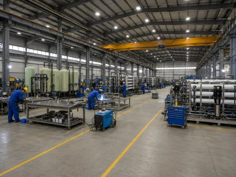
Founded in 2016, Qingdao Hiju Thermal Power Co., Ltd operates from a 70,500 sqm facility with 21,000 sqm of dedicated production workshop space. Our engineering team comprises 78 technicians and 28 engineers structured to handle full project scope — from design review through factory testing to export documentation.
We hold CE, ISO 9001 and ASME-related manufacturing documentation for applicable pressure-rated components. ASME-compliant documentation can be supplied on request where project specifications or local regulations require it. CE and ISO 9001 are standard compliance requirements for textile water treatment system exports — reviewed at supplier qualification and during buyer audits for textile mills in Bangladesh, Vietnam, Indonesia, Turkey, and South Asia.
Our systems have been exported to clients in more than 20 countries and regions, with primary markets in Southeast Asia, the Middle East, Africa, South America and Central Asia. Review our completed engineering projects to verify project type, application and export geography without relying on marketing claims, or browse our full range of industrial water treatment plant solutions by application sector.
Submit your water treatment requirements.
Our engineering team reviews each project against your source water chemistry, dye process specification, and discharge constraints before recommending a treatment train.
Water & process inputs
- Source water analysis — Hardness, TDS, iron, turbidity, pH, conductivity; full laboratory report preferred.
- Dye process type — Reactive, disperse, acid, vat, or other; fibre type (cotton, polyester, nylon, wool).
- Daily water volume — Makeup water demand per day and peak batch demand if applicable.
- Target dyeing bath quality — Conductivity or TDS limit for the dyeing bath and rinsing water circuits.
- Effluent discharge requirement — Local discharge standards for COD, colour, TDS, and daily effluent volume.
Site & project inputs
- Wastewater volume — Daily effluent volume; effluent composition if available — COD, colour, surfactant load.
- Reuse target — What percentage of treated effluent is targeted for reuse and at what quality specification.
- Power supply — Voltage and available amperage at treatment plant location.
- Destination — Country of installation; any local equipment certification requirements for import.
- Project stage — New facility, capacity expansion, or upgrade of existing treatment system.
For rapid dialogue in Southeast Asia, South Asia, or the Middle East, contact our engineering team via WhatsApp or email with your water analysis and dye process specification.
For textile and dyeing facilities that also operate steam boilers for heat-setting and dye fixation — where feed water quality affects boiler life and steam purity — our boiler feed water treatment solutions address the integrated design logic for that connected system. boiler feed water treatment
For aquaculture and agricultural water treatment sites operating adjacent to textile production zones where shared groundwater resources are treated for different end uses, our aquaculture and irrigation water treatment solutions address the biological and agrochemical parameters for those circuits. agriculture water filtration
Explore by product category
Every piece of equipment used in the configurations above belongs to one of these six product families. Browse the full range, specifications, and configuration options.