
Pure Water Storage Tanks
Protecting what your purification system worked to produce. We design every pure water storage tank around one constraint: the upstream system has already done the hard work — the tank must not undo it.
The Storage Problem Most Buyers Don’t Plan For
Pure water does not stay pure on its own. Once an RO or DI system delivers product water into a vessel, three contamination pathways become active — and each requires a specific design response.
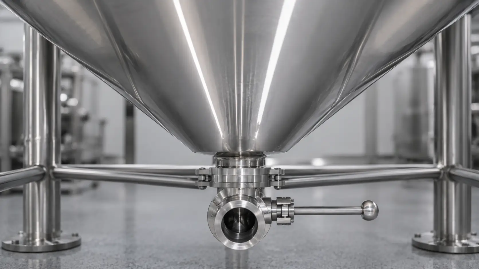
Airborne ingress
Every fill-and-draw cycle moves air through the tank headspace. Without a 0.2 µm hydrophobic PTFE vent filter on the atmospheric port, each cycle draws unfiltered ambient air directly onto the water surface.
Consequence: Particulate and airborne microbes enter water the upstream system has already conditioned.
Biofilm in stagnant zones
Stagnant zones in ambient-temperature pure water systems can support microbial attachment and biofilm development, especially when turnover, sanitization interval, vent filtration, and disinfectant residual are inadequate.
Consequence: Dead zones in tank geometry become biofilm incubators regardless of how clean the incoming water is.
Ionic leaching from incorrect material
Stainless steel releases measurable iron ions in deionized or ultrapure water, elevating conductivity in water the upstream system was specified to keep below a target threshold.
Consequence: Material selection becomes a process boundary decision, not a cost decision.
What Our Pure Water Tanks Are Designed For
This page covers pure water buffer storage: tanks positioned at the output of an RO, DI, or EDI system and upstream of distribution or point-of-use.
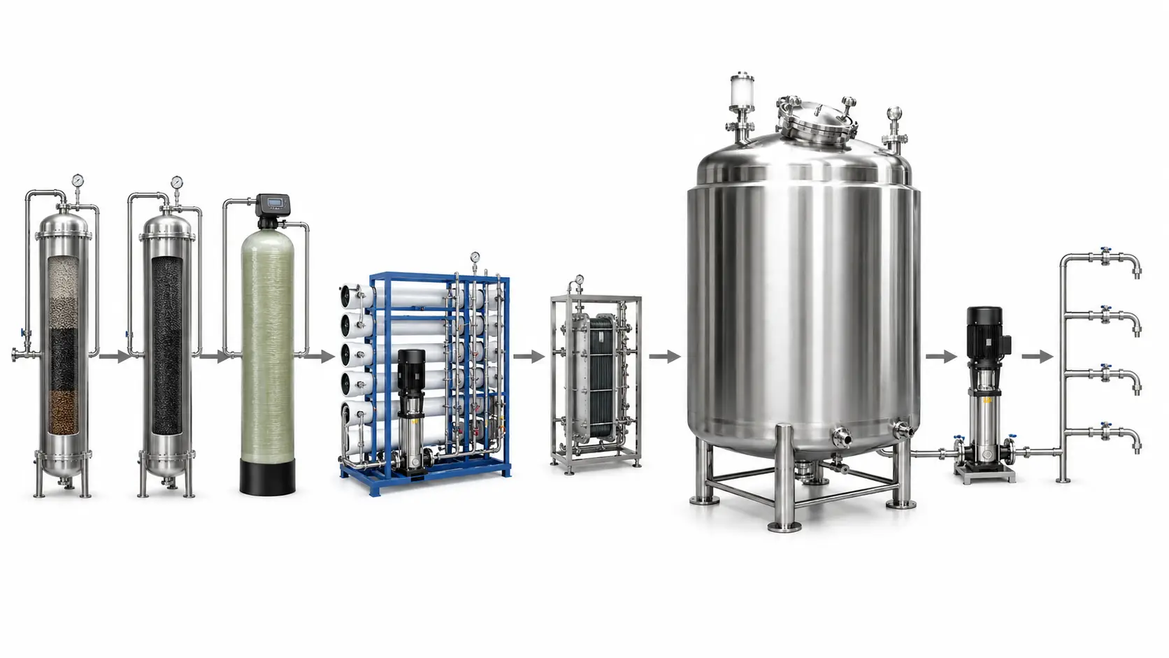
Upstream Sources We Configure For
- RO permeate — single-pass or multi-pass, typical conductivity: 5–50 µS/cm.
- DI water — deionized via mixed-bed or strong acid/base resin systems.
- EDI output — electrodeionization continuous polishing, upstream of pharmaceutical or electronics lines.
Downstream Applications Within Scope
- Pharmaceutical and biotech ingredient water, formulation, and in-place cleaning supply.
- Food and beverage ingredient water, process water, and equipment rinsing.
- Electronics component rinsing and process water for industrial DI grade.
- Cosmetics and personal care formulation water.
- Commercial building post-RO buffer for hotel, hospital, and office projects.
- Chemical processing dilution water.
Outside the Scope of This Product
Raw water and pre-treatment storage belongs in FRP water tanks built for higher-turbidity, corrosive, outdoor pre-treatment conditions. SS316L is suitable for many RO permeate, purified water, food-grade, and industrial DI applications. For high-resistivity DI or ultrapure water systems where metal-ion release, TOC, or particulate contamination is a critical parameter — PVDF, PP, or lined construction should be reviewed. Applications above 1 MΩ·cm should be assessed for non-metallic or lined construction rather than assuming stainless steel is acceptable without water chemistry and validation review. Contact our engineering team to confirm the correct specification.
Choose the Right Material Before Specifying Capacity
Before specifying capacity or accessories, material selection determines whether the tank maintains or compromises the purity your upstream system delivered.
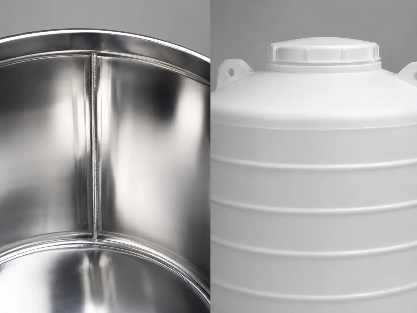
| Material | Applicable Purity Level | Typical Application Context | Key Advantage | Limitation / Boundary |
|---|---|---|---|---|
| SS316L | RO permeate to DI water; pharmaceutical-grade purified water | Pharma production water, food and beverage ingredient water, cosmetics formulation, high-spec industrial DI | Superior chloride corrosion resistance; in-place cleaning and steam sterilization compatible; polished interior surface options | For UPW above 1 MΩ·cm, confirm with engineering — ionic leaching risk requires chemistry and validation review; higher cost than PE for general industrial buffer |
| SS304 | RO permeate; food-grade or commercial-grade pure water; general industrial where SS316L is not required | Commercial building post-RO buffer, food-grade rinsing water, general industrial buffer; chemical dilution water and boiler feed buffer where purity threshold is moderate | Lower cost than SS316L; adequate corrosion resistance for moderate-purity applications | Lower chloride resistance than SS316L; not for high-salinity input or aggressive cleaning chemicals |
| PE (polyethylene) | RO permeate; general industrial buffer where DI or higher purity is not required | General industrial RO output buffer tank; chemical dilution water where operating temperature is ambient and in-place cleaning is not required | Lowest cost; broad chemical resistance; corrosion-free | Not for high-temperature service, in-place cleaning, pharma, or food compliance-adjacent use. PE plastic water tanks |
| FRP | Pre-treatment and raw water stages only — not for pure water output | Raw water storage, pre-treatment holding, outdoor installation in corrosive environments | High corrosion resistance; large-volume structural integrity; outdoor durability | Not for pure water output storage |
When your upstream output is RO permeate at 50 µS/cm or below for general industrial use, PE is adequate and reduces cost. When your output is DI or EDI water for pharma or food production, SS316L is the standard. We will tell you directly which material fits your application — not the most expensive option.
For material grade selection, surface finish, and connection standards in SS304 and SS316L: Stainless steel water tanks.
Pure Water Storage Tank Engineering Features
Each feature addresses a specific failure mode. The entry below each one names what happens to stored water purity if the feature is omitted.
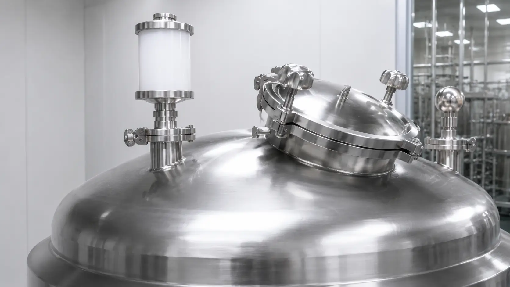
Sloped Conical Bottom + Full-Bore Drain
Drainability is confirmed collectively — bottom slope, outlet position, drain size, internal surface finish, and weld profile. Slope alone does not guarantee complete drainage.
Without: Flat-bottom tanks retain standing water — the primary biofilm incubation site.
0.2 µm Hydrophobic PTFE Vent Filter
The atmospheric vent is the largest contamination risk on an otherwise sealed tank. Hydrophobic PTFE membrane resists wetting under condensation or high humidity. Sized to maximum fill/draw airflow — not tank volume alone.
Without: Each fill/draw cycle introduces unfiltered ambient air; undersized filter creates vacuum lock.
Clean-In-Place (CIP) Spray Ball Port
Spray ball at tank dome delivers cleaning solution to the full interior surface via a dedicated full-bore cleaning inlet matched to pressure requirement.
Without: Interior surfaces above water line are not reached by recirculating cleaning solution.
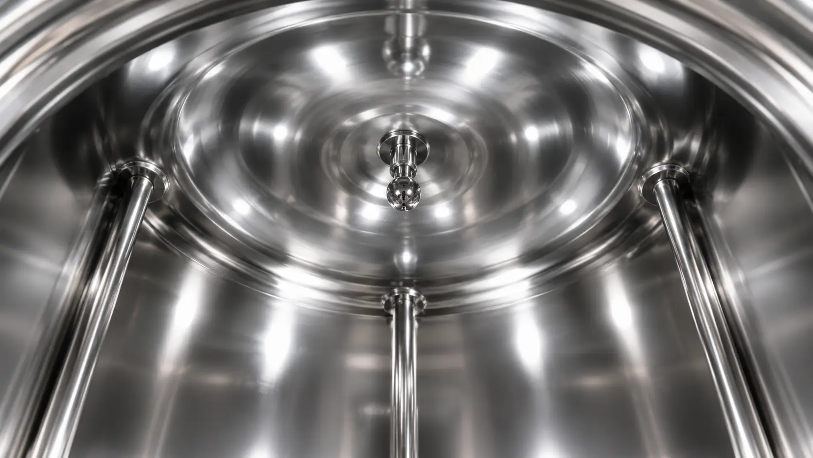
Recirculation Loop Nozzles + UV Port
Dedicated outlet and return nozzles support loop velocity — we review 0.5 m/s or higher as an engineering target, confirmed against temperature, sanitization strategy, and validation requirements. A dedicated UV port positions the sterilizer in the return leg; UV dose is reviewed by flow rate, transmittance, lamp aging, and validation requirement — 30 mJ/cm² is a starting reference only.
Without loop nozzles: Laminar boundary layers at reduced velocity increase biofilm risk.
Instrumentation, Insulation, and SIP Option
Level sensor nozzles, conductivity probe port, sampling valve, and temperature sensor are positioned without dead-leg extensions. Optional polyurethane foam insulation and trace heating maintain temperature in hot-loop or cold-climate installations. Pharma-grade projects may specify a dedicated steam inlet and condensate drain nozzle rated to 121°C — SIP cannot be retrofitted.
Note: Vent filter integrity test requirement for pharma/biotech projects should be confirmed at commissioning.
Configuration and Specification Reference
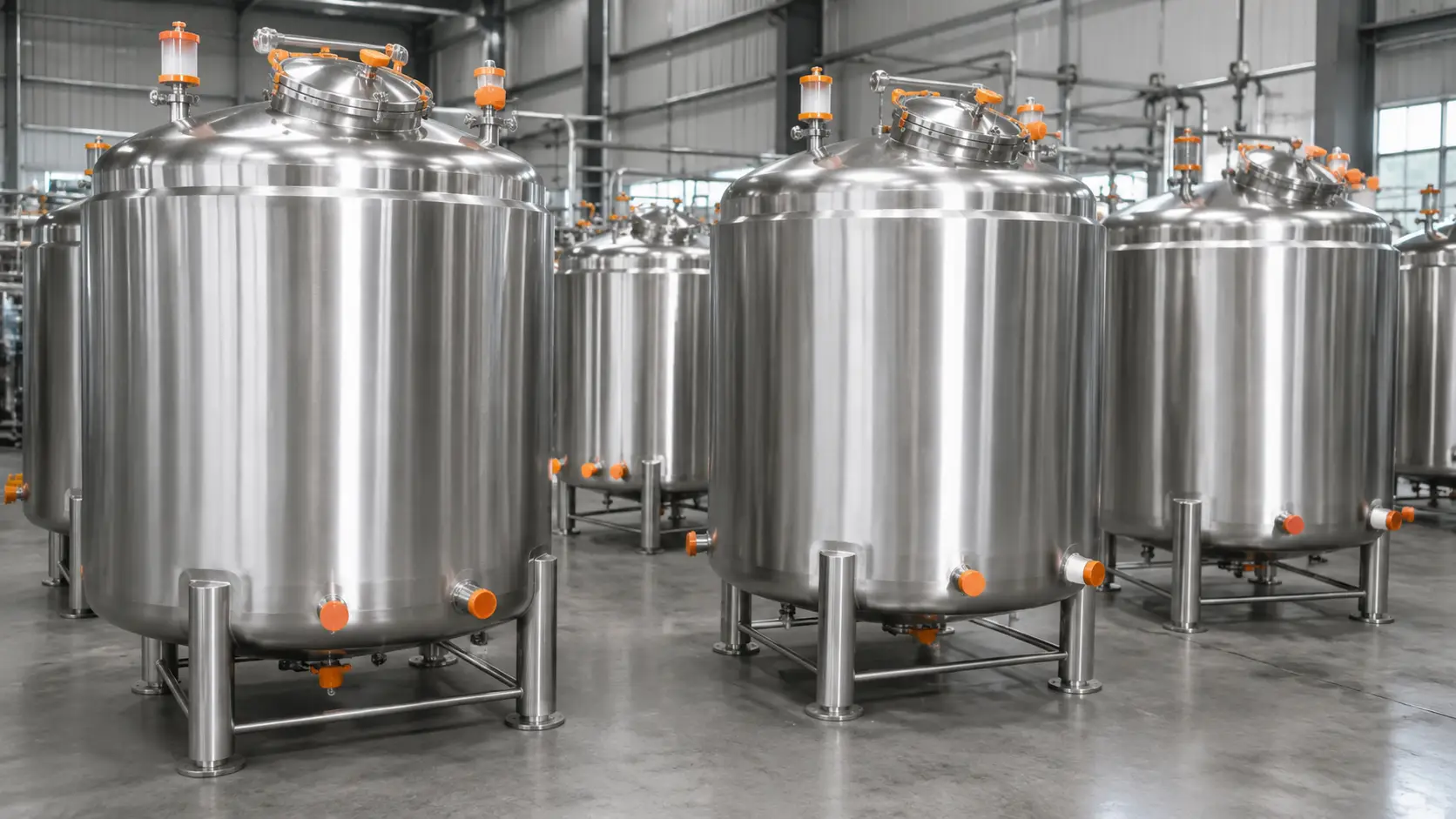
All configurations are reviewed against upstream system output quality and downstream application before fabrication — not selected from a fixed catalog.
| Parameter | Range / Options |
|---|---|
| Capacity | 100 L–30,000 L; standard sizes: 500, 1,000, 2,000, 5,000, 10,000, 20,000 L |
| Tank material | SS316L primary; SS304 secondary; PE available via the PE tanks specification path |
| Surface finish | Mechanical polish or electropolish; finish grade discussed during engineering review |
| Bottom design | Conical sloped for in-place cleaning (slope confirmed per project); flat for general buffer |
| Vent filter | 0.2 µm hydrophobic PTFE cartridge, field-replaceable connection |
| In-place cleaning provisions | Spray ball port, cleaning inlet nozzle, and full-bore drain valve as optional module |
| Recirculation nozzles | Outlet and return nozzles sized to loop flow rate |
| UV port | Dedicated loop nozzle pair for UV sterilizer — optional |
| Level measurement | Float switch or ultrasonic sensor nozzle for continuous PLC output |
| Working temperature | 5 °C–95 °C standard; up to 121 °C SIP-rated — confirmed per project |
| Shape | Vertical cylinder standard; horizontal for space-constrained sites; custom |
| Connection standard | Tri-clamp, DIN flange, threaded DN40–DN200; confirmed per application |
| Insulation / support | Polyurethane foam jacket optional; SS sanitary legs standard; skid frame optional |
| Working pressure | Atmospheric vented (standard); closed low-pressure to 0.3 MPa (engineered per project); ASME pressure configuration (on request) — see note below |
Pressure Class Clarification
- Atmospheric open-vent — standard; vented through 0.2 µm hydrophobic filter; not a pressure vessel
- Closed low-pressure to 0.3 MPa — nozzle, gasket, wall thickness, and relief requirement confirmed before production; design pressure, test pressure, and design temperature specified at order stage
- ASME pressure configuration — available on request; code stamp, working pressure, test pressure, relief valve connection, and applicable destination code confirmed before quotation
Pure Water Storage Applications by Industry
Pure water storage tanks are configured differently for each downstream application — compliance context, cleaning requirements, and material specification vary by industry.
Pharmaceutical and Biotech
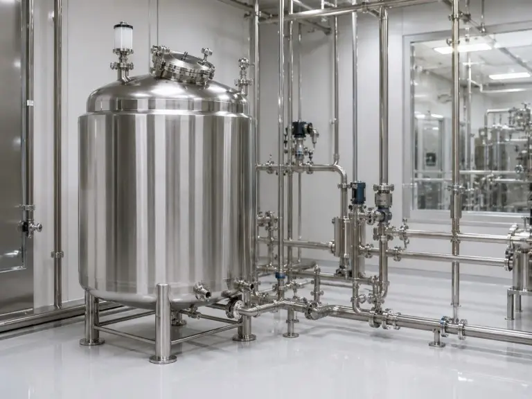
The tank is a GMP-adjacent process asset: biofilm or particulate ingress can compromise batches produced with otherwise correctly specified water. SS316L with conical drain, in-place cleaning spray ball, vent filter, recirculation loop connections, and sampling valve is the standard production-grade configuration.
deionized water filtration system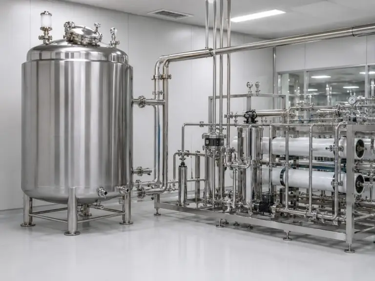
Food and Beverage
Ingredient water and equipment rinsing water require cleanable surfaces, no dead legs, no porous wetted materials, and filtered vent protection. SS304 or SS316L is selected by cleaning chemistry; SS316L is required where aggressive cleaning chemicals or high-chloride environments apply.
bottled water plants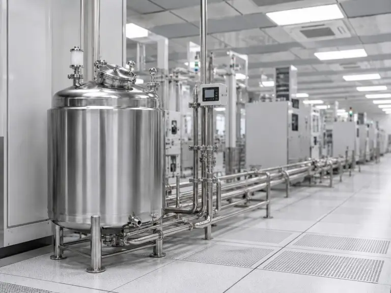
Electronics and Semiconductor
SS316L tanks fit industrial-DI grade work — PCB rinsing, component cleaning, and process water below semiconductor-grade UPW. For high-resistivity applications above 1 MΩ·cm, non-metallic or lined construction should be reviewed before specifying stainless, as ionic leaching requires water chemistry and validation review to confirm.
Hotel and Commercial Buildings
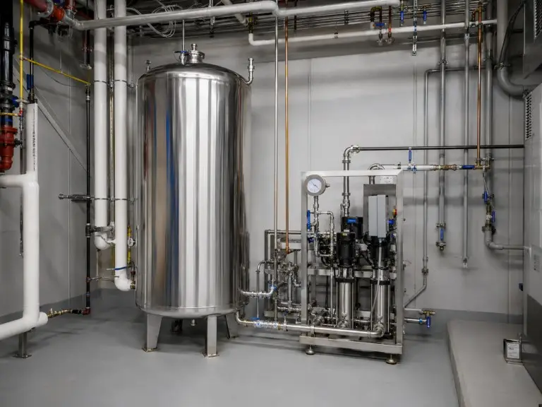
Post-RO buffer tanks sit between RO output and the building distribution header; 30–60 minutes of peak downstream demand is the starting point. SS304 or PE is common, with vent filter integrity, level control, and recirculation loop connection used to prevent stagnation.
water filtration systems for commercial use| Industry Context | Key Engineering Consideration | Typical Specification |
|---|---|---|
| Pharmaceutical and Biotech | Tank is a GMP-adjacent process asset. Biofilm or particulate ingress can compromise batches. Validation documentation required. Final compliance must be confirmed against process specification, validation protocol, and applicable local standard. | SS316L · conical drain · spray ball · vent filter · recirculation nozzles · sampling valve · fabrication documentation for validation review |
| Food and Beverage | Ingredient water and rinsing water require cleanable surfaces, no dead legs, no porous wetted materials, and filtered vent protection. Cleaning chemistry determines SS304 vs SS316L. | SS304 or SS316L · vent filter · no dead-leg branches · smooth interior finish |
| Electronics — Industrial DI | PCB rinsing and component cleaning below semiconductor-grade UPW. Above 1 MΩ·cm resistivity, non-metallic or lined construction should be reviewed before specifying stainless. | SS316L for industrial DI · PVDF or PP-lined for high-resistivity UPW · confirm resistivity target at inquiry |
| Hotel, Hospital, Commercial Building | Post-RO buffer between RO skid and distribution header. 30–60 minutes of peak demand is the starting point. Level control, vent filter, overflow routing, and recirculation connection determine long-term stability. | SS304 or PE · vent filter · level sensor · overflow fitting · recirculation loop connection |
Common Specification Mistakes and Their Consequences
These specification errors appear consistently in failure-mode reviews for systems where storage was treated as passive infrastructure rather than a designed process stage.
Specifying tank capacity against system output rate alone.
Tank capacity should be sized against the gap between upstream production rate and downstream consumption rate. A 5 m³/h RO system feeding a line that draws at 3 m³/h for 8 hours and 0 m³/h for 16 hours requires a different buffer volume than a continuous 5 m³/h draw; undersized buffer tanks cause RO high-pressure pump short-cycling and reduce membrane life.
Omitting the vent filter.
An open atmospheric vent is the single fastest way to re-contaminate stored pure water, especially on general industrial tanks where purity can appear less critical. A 0.2 µm hydrophobic vent filter is a low-cost addition; a biofilm event requiring system remediation is not.
Installing a flat-bottom tank in an in-place cleaning system.
A flat-bottom tank drained through a side-wall outlet always retains water in the sump below the outlet. That volume cycles through every cleaning sequence without being displaced, becomes progressively contaminated, and re-contaminates the cleaned tank interior on the next fill cycle.
Using standard stainless steel fittings in a DI water loop.
Standard carbon steel or common-grade stainless threaded fittings in a DI water distribution loop release iron ions into the water column. The tank material may be correct, but a single carbon steel fitting in a pump connection can elevate conductivity at point of use, so every wetted surface must be reviewed.
A 6D rule is commonly referenced as a dead-leg design guideline for high-purity water loops.
A 6D rule is commonly referenced as a design guideline — the final dead-leg requirement should follow the buyer’s validation standard, applicable hygienic design guidance, and site-specific engineering review. This distribution loop constraint affects how we position tank outlet and return nozzles relative to the first point-of-use take-off.