
Raw Water & Intermediate Tanks
Two tanks anchor the hydraulic foundation of every industrial water treatment system: a raw water tank at the system entry point, and an intermediate tank between treatment stages. We supply raw water and intermediate tanks — in stainless steel, PE/HDPE, and FRP construction, from 0.5 m³ to 200 m³ — configured to match the specific process position, water chemistry, downstream equipment, and installation environment of each project.
Specify by function and system position first, then choose material. If you already know the material, our product pages go further into construction and configuration details.
Two Positions, One Product Family
Most suppliers treat “raw water tank” as a single product type — a large vessel at the system inlet. That framing misses half the engineering question. In a typical industrial or commercial water treatment system, tanks appear at two structurally different positions, each with different sizing logic, different water chemistry exposure, and different consequences for what is downstream.
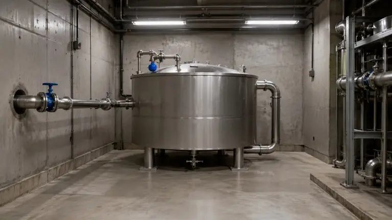
Raw Water Tank — System Entry Point
The raw water tank receives untreated source water directly from the supply point — municipal main, borehole pump, river intake, or coastal desalination feed. Its function is to absorb source-side flow variation, allow gross suspended solids to begin settling, and deliver a stable, steady-flow supply to the first pre-treatment stage. The tank receives and holds; it does not treat. Chemical dosing can occur here, but coagulation and flocculation require dedicated downstream contact chambers.
Sizing benchmark: ≥ 30–60 minutes of pre-treatment throughput at peak demand. A 10 m³/h pre-treatment system starts at 5–10 m³. Undersizing forces pre-treatment equipment to respond directly to source pressure fluctuations, increasing mechanical wear and raising bypass risk during demand surges.
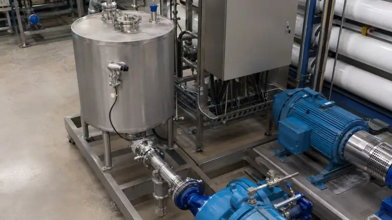
Intermediate Tank — Inter-Stage Buffer
The intermediate tank sits between two treatment stages — most commonly on the feed side of the RO high-pressure pump, after multi-media filtration or softening and before the membranes. Its function is to decouple upstream production rate from downstream demand rate. Without a buffer, the high-pressure pump runs against variable suction pressure; when suction head drops below the pump’s cavitation threshold, each restart under those conditions damages the impeller and seals.
Sizing benchmark: ≥ 15 minutes of average RO demand as baseline. A 5 m³/h RO system starts at 1.25 m³; food production and hotel systems commonly require 20–30 minutes. Electrode level sensing integrated with pump start/stop is standard to prevent low-level pump starts.
Where Each Tank Fits in Your Treatment System
The material grade, capacity, and pressure class for each tank follow directly from its position in the system — the position determines what water chemistry the vessel sees and what failure condition an undersized or wrong-material tank creates downstream.
Source Water → Raw Water Tank → Pre-treatment: filter, softener → Intermediate Tank → High-pressure Pump and RO → Product Water
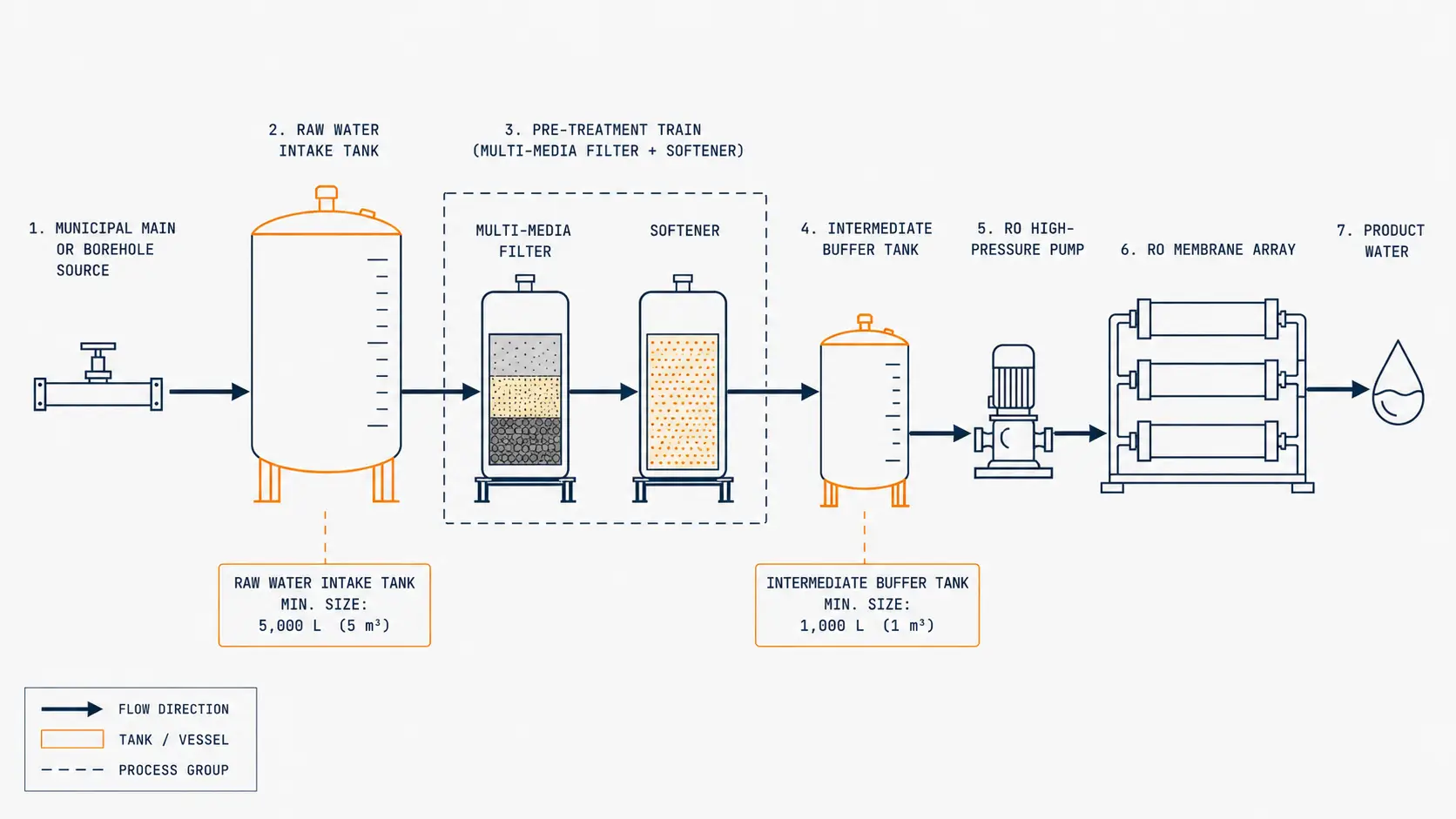
Each position imposes different chemical exposure on the tank. The raw water tank sees the highest variability — turbidity spikes, variable chlorine content, and the highest biological load in the system. The intermediate tank sees pre-treated but not yet purified water. A post-RO product water buffer sees the highest-purity water in the system and requires sealed, sanitary construction to prevent recontamination. Material grade, surface finish, and accessory selection follow directly from this position logic.
Select the Right Material for the Water Chemistry and Process Position
The three construction materials in our range cover distinct operating envelopes. Specifying the wrong material for a given process position results in internal corrosion, biological fouling accumulation, UV degradation of the vessel wall, or structural failure under temperature load — all avoidable at the project specification stage.
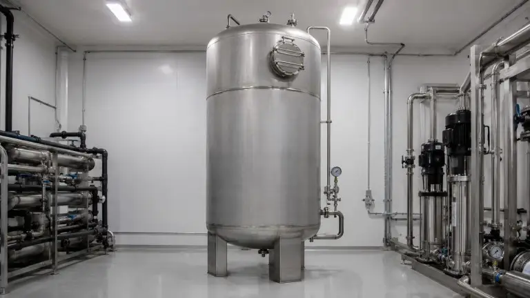
Stainless Steel (SS304 / SS316 / SS316L)
SS304 suits municipal supply intake, pre-treatment feed, hotel and commercial building water holding, and food-contact applications with non-aggressive chemistry. Service temperature up to 80°C, low-chloride freshwater service. As a preliminary guide, source water with chloride consistently in the 200–250 mg/L range and above is reviewed project by project; final grade selection depends on chloride level, temperature, pH, cleaning chemistry, and weld requirements. Electropolished interior (Ra ≤ 25 microinch) available for sanitary-grade applications.
SS316 / SS316L is specified for higher-chloride applications where SS304 has been reviewed and found unsuitable, seawater desalination pre-treatment, food and beverage sanitary circuits with direct food-contact downstream, and pharmaceutical or process water service. SS316L eliminates carbide precipitation risk at welded heat-affected zones.
Final compliance must be confirmed against the user’s process specification, validation protocol, and applicable local standard.
stainless steel water tanks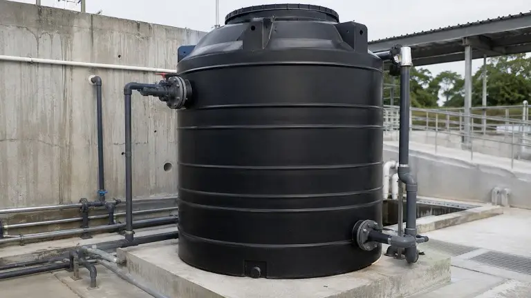
PE / HDPE
Suited for intermediate service where residual oxidants are present in feed water, outdoor installations in moderate-temperature climates, and lower-cost configurations for light industrial applications where water temperature remains consistently below 60°C. Smooth HDPE interior requires no welding on most configurations, reducing contamination risk from weld porosity in intermediate-stage service.
Temperature is the firm constraint: continuous service above 60°C causes progressive creep deformation in HDPE regardless of water chemistry. This applies equally to feed water temperature and outdoor ambient wall temperature. Not suitable for high-temperature process service, food and beverage sanitary certification, or sustained high-UV outdoor exposure without UV-stabilized compound specification.
PE plastic water tanks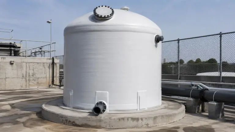
FRP / GRP
Standard choice for exposed outdoor plant rooms in high-UV, high-humidity, or high-ambient-temperature environments — Southeast Asia, the Middle East, and coastal Africa. Also specified for acid or alkali intermediate service at elevated concentrations, high-chloride source water, and larger-capacity outdoor raw water intake tanks in the 20–200 m³ range where weight and cost-per-volume favour FRP over stainless steel. Smooth interior resin coat with no metallic corrosion pathway.
Service temperature rating depends on resin system, laminate construction, and structural design; confirm by resin data sheet before specifying above ambient water temperature service. Not suitable for sanitary food and pharma service where electropolished metal is the specification standard, or pressurized service above 0.3 MPa unless the laminate design is specifically engineered for that pressure class.
Final compliance must be confirmed against the user’s process specification, validation protocol, and applicable local standard.
FRP water tanksEngineering Parameters and Configuration Specifications
| Parameter | Specification |
|---|---|
| Material options | SS304, SS316/SS316L, PE/HDPE, FRP/GRP |
| Capacity range | 0.5 m³ – 200 m³ |
| Configuration | Vertical (standard); horizontal for height-constrained installations |
| Working pressure – standard | Atmospheric (open tank) |
| Working pressure – pressurized intermediate | 0.1 – 0.3 MPa |
| Service temperature – SS | Up to 80°C |
| Service temperature – PE/HDPE | Up to 60°C for continuous liquid service; outdoor solar wall heating, short-term excursions, wall stress, and tank geometry must be reviewed separately |
| Service temperature – FRP | Resin-system and laminate-design dependent; confirm by resin data sheet before specifying above ambient water temperature service |
| Inlet/outlet connections | Flanged DN25-DN300; position and orientation customizable |
| Surface finish – industrial SS | Pickled and passivated |
| Surface finish – food/pharma SS | Electropolished, Ra ≤ 25 microinch equivalent |
| Surface finish – PE/HDPE | Smooth HDPE interior |
| Level control options | Float valve; 3-electrode level controller (high/low/dry-run); ultrasonic level sensor |
| Standard accessories | Overflow drain, vent port, access manhole (all tanks ≥ 0.3 m³), bottom drain valve, level gauge |
| Optional accessories | Insulation jacket, anti-vortex baffle at outlet nozzle, SCADA-compatible level transmitter, sample valve |
| Installation environment | Indoor or outdoor; UV-stabilized compound for outdoor PE/FRP |
| Sizing – raw water tank | ≥ 30–60 minutes of pre-treatment throughput at peak demand as an engineering starting point; longer reserve required where source interruption, filter backwash, or maintenance windows are design constraints |
| Sizing – intermediate tank | ≥ 15 minutes average downstream demand as an engineering starting point; 20–30 minutes for continuous-production applications; final sizing confirmed against pump NPSH, low-level cutoff position, and peak demand profile |
| Certifications | CE / ISO 9001; ASME pressure-vessel documentation available on request — standard atmospheric open tanks are not ASME pressure-vessel products |
| OEM/ODM | Available; custom dimensions, nozzle layouts, and accessories to customer drawing |
The values above are Hiju preliminary design targets for raw water and intermediate tank configurations. Final specifications depend on water chemistry, source type, downstream equipment, installation environment, and project-specific engineering review.
Orientation, Level Control, and Accessories for Your Installation
Tank configuration at each position in the treatment train is governed by installation geometry, downstream equipment requirements, and the water chemistry at that stage. Our team of 28 engineers and 78 technicians reviews project-specific inputs before confirming a configuration drawing and bill of materials.
Vertical vs Horizontal Orientation
Vertical tanks are standard for most industrial installations — minimal floor footprint, consistent liquid cross-section for level sensing. Horizontal tanks are specified when ceiling clearance is the binding constraint: basement plant rooms, containerized treatment systems, and rooftop installations with structural height limits.
Level Control
Float valves give mechanical, non-powered refill control for raw water tanks where automation is not required. Electrode level controllers (three-electrode: high alarm, operational low, dry-run cutoff) are standard on intermediate tank builds and integrate with the downstream pump start/stop circuit. Ultrasonic sensors are specified for high-turbidity raw water tanks where electrode fouling is a concern; they integrate with SCADA or BMS via 4–20 mA output.
Nozzle Position and Anti-Vortex Baffle
For raw water tanks receiving surface water above 30 NTU, inlet nozzle is positioned at the upper third of the tank wall to prevent turbulence from disturbing the settled sediment layer. Outlet nozzles on intermediate tanks feeding high-pressure pumps include an anti-vortex baffle as standard — swirl-induced air entrainment at the outlet causes impeller cavitation, and the baffle eliminates that pathway.
Insulation Jacket
Not required for most Southeast Asia, Middle East, or equatorial Africa installations. Specified for cold-climate installations where raw water intake drops below 5°C, hot water pre-treatment systems requiring temperature maintenance, and food production applications with tight feed temperature specifications on the intermediate tank.
UV-Stabilized Exterior Compound
UV stabilization is a compound selection at manufacture, not a coating applied after fabrication. For outdoor PE and FRP tanks, UV-stabilized compound is standard in our supply. Unstabilized PE compounds degrade under sustained solar exposure — beginning with surface embrittlement and progressing to structural failure over 2–4 years in equatorial or high-UV environments.
Where Raw Water and Intermediate Tanks Are Specified
Food and Beverage Processing — Intermediate Tank for Production Line Continuity
Food and beverage production lines require continuous, stable water supply to the RO system serving the process. An interruption at the RO feed side — caused by an undersized intermediate tank allowing the feed pump to cavitate, or by a supply gap during a pre-treatment backwash cycle — results in production downtime that costs far more than the buffer tank itself.
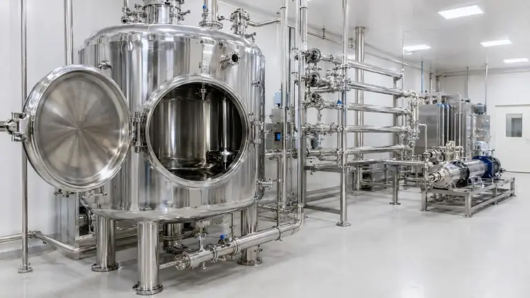
For a food plant operating a 3 m³/hour RO system on a two-shift production schedule, we configure a 1.5–3 m³ intermediate tank between the pre-treatment train and the RO high-pressure pump. This sizing provides 30–60 minutes of RO demand buffering while the pre-treatment equipment is in backwash or ion-exchange regeneration mode. SS316 or SS316L with an electropolished interior is the standard material for food and beverage intermediate tanks where the downstream water is part of a sanitary circuit contacting food products directly.
Final compliance must be confirmed against the user’s process specification, validation protocol, and applicable local standard.
bottled water plants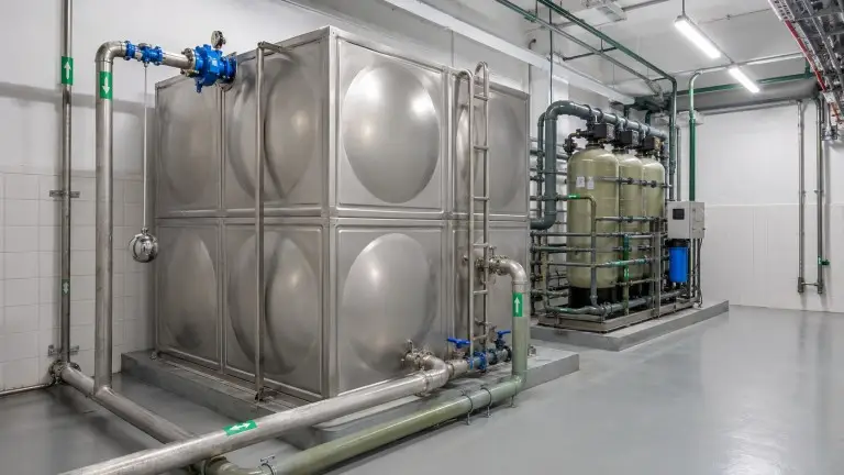
Hotel and Commercial Building — Raw Water Intake Before Building Treatment
Hotels and commercial buildings in Southeast Asia, the Middle East, and coastal Africa frequently operate on municipal water supplies with variable pressure, seasonal turbidity variation, and intermittent service during peak demand periods. A raw water intake tank at the building entry point — before the internal treatment and distribution system — decouples the treatment plant from source supply variation.
We configure hotel raw water intake tanks at 1–4 hours of building peak daily demand, depending on the reliability of the municipal supply at the project site. For a mid-scale hotel running a 100 m³/day water treatment system where municipal supply gaps of 2–3 hours per day are routine, a 10–15 m³ raw water intake tank allows the treatment system to maintain continuous operation through those interruptions. SS304 is standard for this application; outdoor plant room installations in high-humidity rooftop or exposed-basement environments, where tank weight is a structural concern, may use UV-stabilized FRP.
water filtration systems for commercial use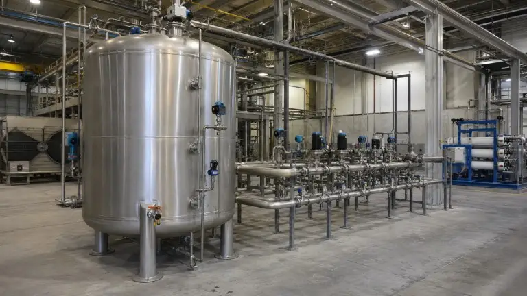
Light Manufacturing and Industrial — Buffer Before Boiler Feed or Process Distribution
Manufacturing facilities using treated water for boiler feed, cooling tower makeup, or process rinsing typically operate in production cycles with defined peak demand windows. An intermediate tank between the water treatment system and the boiler feed header allows the upstream treatment equipment to run at a continuous rate while the process side draws at variable rates throughout the shift.
For a 20 m³/day boiler feed water system running at 2 m³/hour during a single production shift, a 2–3 m³ intermediate tank buffers 60–90 minutes of process demand without cycling the upstream softener or pre-treatment feed pump. PE/HDPE is a common material choice for this role when the intermediate water contains residual dosing chemicals and the service temperature remains consistently below 60°C. If the boiler feed pre-treatment includes high-temperature flash degassing or hot lime softening, SS or FRP replaces PE in the configuration.
Municipal and Infrastructure Backup — Raw Water Reserve Before Distribution
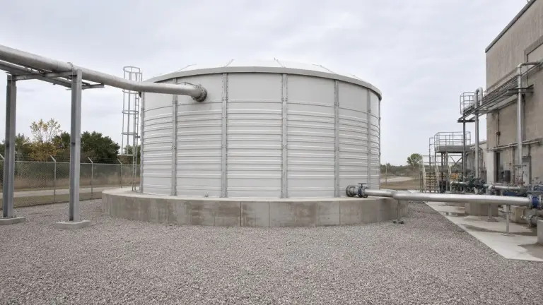
Infrastructure backup installations — remote pump stations, multi-user distribution points, and small municipal treatment plants serving several hundred to several thousand cubic meters per day — require raw water reserve capacity sized for peak distribution demand plus a maintenance reserve window. FRP tanks in the 20–200 m³ range are the standard configuration for these outdoor applications: flanged connections DN100–DN200 accommodate the flow rates at this scale, UV-stabilized exterior compound provides long service life without the protective coating maintenance required on epoxy-lined or painted steel tanks, and FRP’s structural independence from metallic corrosion is particularly relevant in coastal or industrial-atmosphere environments.
Specification Errors That Cause Downstream Failures
Undersizing the intermediate tank and accepting pump cycling.
An intermediate tank sized below 10–12 minutes of RO throughput at peak demand causes the high-pressure pump to cycle repeatedly through its start/stop sequence during a single shift. Each pump restart under low-suction pressure exposes the impeller and seals to a momentary cavitation event — an avoidable maintenance cost that exceeds the price difference between a correctly sized and undersized tank well within the first year of operation.
When finalising configuration, the outlet elevation, usable volume above the low-level cutoff, and suction pipe losses should be checked against the pump’s required NPSH to confirm the tank design eliminates the low-suction condition it is intended to prevent.
Using PE/HDPE above its temperature service limit.
PE/HDPE tanks must not be used where feed water temperature consistently exceeds 60°C, or where outdoor ambient temperature in a hot-climate installation subjects the tank wall to sustained near-threshold conditions. FRP resolves the temperature constraint while preserving chemical resistance; SS resolves both temperature and sanitary-grade requirements. Framing the PE/HDPE limit as “approximately 60°C” and then designing to 58°C is not an appropriate engineering practice — specify the correct material for the service envelope.
Over-specifying SS316 for standard fresh-water municipal intake.
SS316 is the correct grade when source water chloride exceeds approximately 250 mg/L, for saline or coastal source water, and for food and beverage sanitary circuits. For a standard municipal fresh-water raw water intake tank with low-chloride source water and no food-contact specification, SS304 provides equivalent performance. Specifying SS316 in those conditions increases project cost without engineering justification, and it signals to procurement engineers that the specification was not reviewed against the actual water chemistry.
Omitting level control on the intermediate tank.
An intermediate tank without automated level sensing connected to the downstream pump creates either an overflow condition — product water loss and potential contamination on a post-RO buffer — or a pump dry-run condition that damages the pump impeller at start. Electrode level controllers integrated with the pump start/stop circuit are standard on our intermediate tank builds. Level control is not an optional upgrade; it is the mechanism by which the intermediate tank actually protects the downstream pump.
Treating the raw water tank as a settling clarifier.
A raw water tank allows gross suspended solids to begin settling, but it is not engineered as a clarifier. Source water with turbidity above 50 NTU, high iron content, or significant biological load needs dedicated pre-treatment equipment — coagulation, flocculation, and sedimentation stages — downstream of the intake tank. Expecting the raw water tank to reduce turbidity from 200 NTU to a filtration-ready 5 NTU is a design error that will result in rapid media fouling and shortened backwash intervals in the downstream filter.
Ignoring sediment accumulation access on high-turbidity raw water tanks.
Raw water tanks receiving surface water, canal intake, or seasonal borehole water with variable turbidity will accumulate sediment in the tank base. A tank without a bottom drain valve and without an access manhole makes routine sediment removal impractical. We include both as standard on all raw water tanks for high-turbidity applications. Inspection and cleanout intervals of 3–12 months are typical for industrial installations, depending on seasonal source water quality variation.
What to Include in Your Configuration Inquiry
The faster we receive complete project data, the faster our engineering team can return a configuration drawing with dimensions, nozzle layout, material recommendation, and accessories list. For each inquiry we ask for:
- Water source type — municipal supply, borehole or well, river or canal surface intake, or brackish/coastal groundwater
- Daily volume required — m³/day; include peak hourly flow rate if known
- Tank position in the system — raw water intake or intermediate buffer; specify between which stages
- Downstream equipment — RO system, high-pressure pump, softener, UV sterilizer, filtration, boiler, or distribution header
- Available footprint and height clearance — floor area in meters and ceiling height; state vertical or horizontal preference
- Working pressure class — atmospheric open tank or pressurized; specify pressure in MPa
- Installation environment — indoor plant room or outdoor; climate region; UV exposure level; ambient temperature range
- Source water quality data if available — TDS, chloride concentration, pH, turbidity, temperature; partial data is useful
- Material preference if known — SS304, SS316, PE/HDPE, or FRP/GRP
- Project timeline and destination country — shipping destination and required delivery schedule for engineering and production