
Insulated Water Tanks
Treated water that leaves an RO system, softener, or chilled water circuit arrives at a defined temperature. If that temperature drifts during storage, downstream processes are forced to compensate: heating cycles activate prematurely, process chemistry falls outside tolerance, boiler efficiency degrades, or HVAC distribution setpoints fail to hold. We build insulated water tanks to eliminate that drift with stainless steel construction, closed-cell polyurethane foam insulation, and engineering matched to the specific thermal gap between your stored-water temperature and your installation environment.
Why Water Temperature at Storage Matters to Your Process
Temperature instability at the storage stage is a symmetric risk — it runs in both directions. The four engineering scenarios below are the most common triggers for an insulated tank specification.
Outdoor high-ambient: RO permeate or process water
In Southeast Asia, the Middle East, and tropical Africa, outdoor ambient regularly reaches 38–45°C. A post-RO permeate tank holding water at 25°C faces a continuous ΔT of 13–20°C through the tank wall. In warm stored-water conditions with long retention time or low disinfectant residual, microbial regrowth risk increases — forcing the downstream circuit to handle water outside specification.
q = U × A × ΔT — heat gain rate scales directly with ΔT and exposed surface area
Hot water buffer: sanitary, hotel, hospital, institutional
Water maintained at 65–80°C loses heat continuously to ambient. Uninsulated or under-insulated tanks force heating loops to activate more frequently, increasing energy cost and thermal cycling stress. Below 60°C, commercial hot water supply requirements in hospitality and institutional facilities are not satisfied.
Minimum: 60°C — sustained sanitary hot water delivery threshold
HVAC chilled water: tropical plant rooms
A chilled water buffer at 5–15°C in a 38°C outdoor plant room faces a ΔT of 23–33°C driving heat inward. In a high-ambient installation, an under-insulated buffer tank gains temperature faster than the chiller can replenish cold volume — defeating the purpose of the buffer entirely.
100 mm PU foam — starting point for outdoor chilled buffer in tropical climates
Wall structure: from inner shell to outer jacket
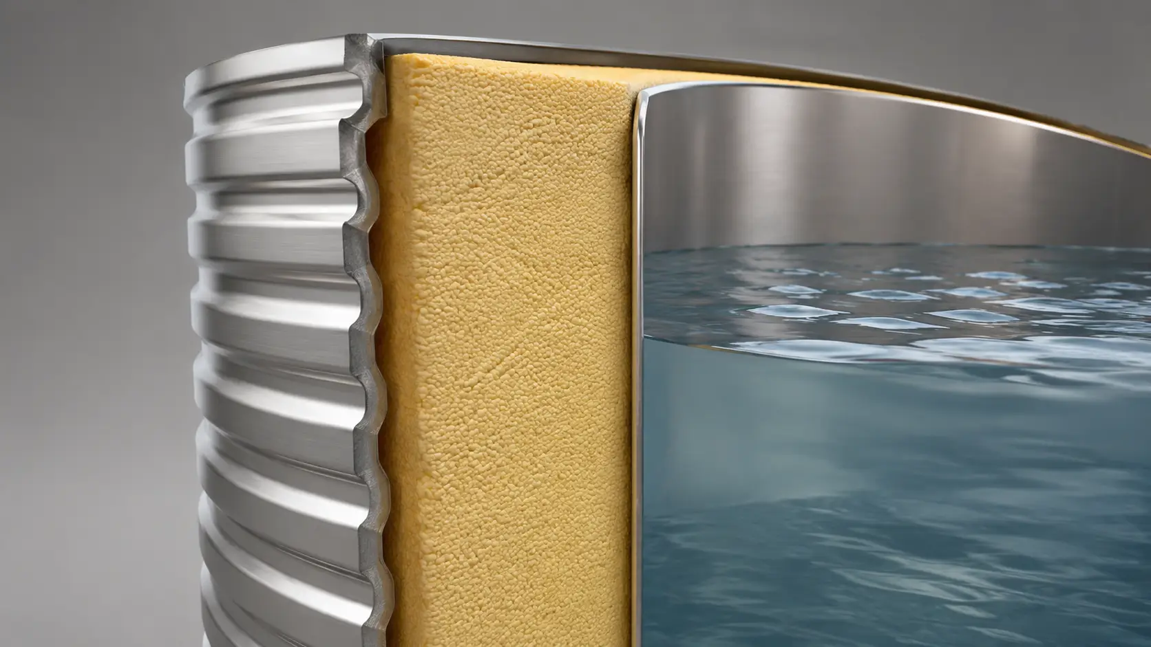
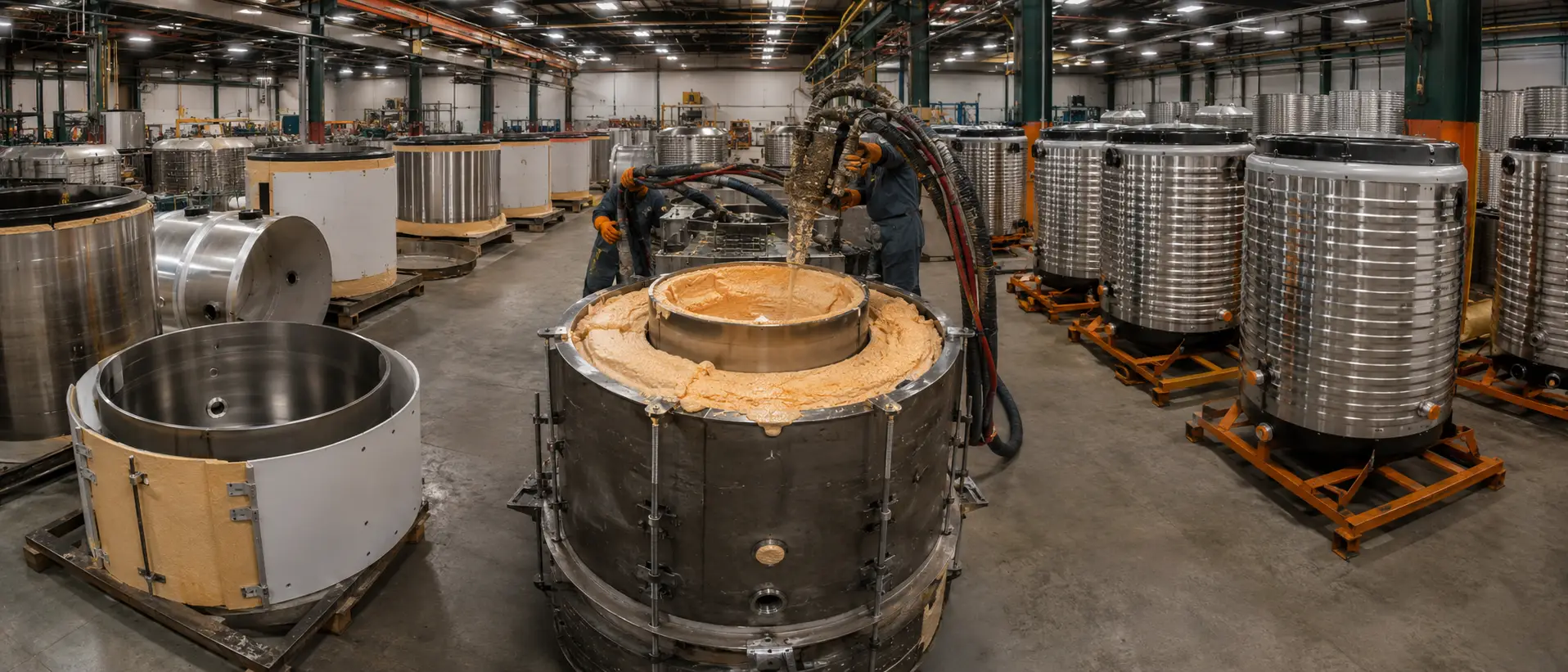
Inner shell in SUS304 or SUS316L, followed by closed-cell PU foam at k ≤ 0.025 W/(m·K), and an outer protective jacket. Closed-cell PU resists moisture ingress and maintains insulating properties in humid tropical environments where glass wool degrades. All three layers are factory-assembled under a single QC chain.
k ≤ 0.025 W/(m·K) — industry benchmark for factory-integrated PU foam insulation
Where Insulated Tanks Fit in a Water Treatment System
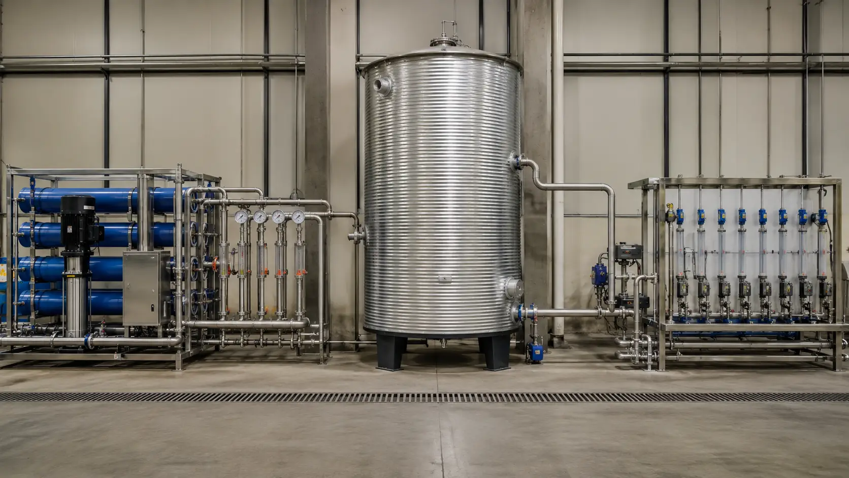
Insulated water tanks are the thermal boundary between upstream treatment and downstream process use. The five integration points below show where each configuration connects in a complete treatment train.
| Integration Point | Stored Water Type | Temp Window | Thermal Challenge | Key Downstream Connection |
|---|---|---|---|---|
| Post-RO Permeate Storage | RO permeate, low-TDS | 20–28°C | Heat gain from outdoor ambient raises temperature, increasing microbial risk in warm conditions with reduced turnover | Distribution header / UV disinfection / process line |
| Post-Softener Process Buffer | Softened water | 20–40°C | Ambient heat gain causes unwanted temperature rise; scaling risk increases at heat exchange boundaries downstream | Boiler feed pump / heat exchanger / process header |
| Pre-Boiler Hot Water Buffer | Heated feed water | 60–80°C | Heat loss to ambient forces frequent boiler activation; temperature variability at boiler inlet reduces thermal efficiency | Boiler feed line |
| HVAC Chilled Water Buffer | Chilled water | 5–15°C | Heat gain from ambient (ΔT 23–33°C in tropical plant rooms) can outpace chiller replenishment rate; defeats buffer purpose | Air handling unit / fan coil circuit |
| Sanitary Hot Water Buffer | Hot domestic/process water | 60–85°C | Heat loss during standby periods forces heating plant to respond in real time; below 60°C creates unacceptable risk for bottled water plants and water filtration systems for commercial use | Hot water distribution ring main / CIP supply |
Configuration Variables and Selection Guide
The engineering variables that drive insulated tank specification are interconnected. Insulation thickness cannot be selected independently of ambient temperature, which cannot be separated from installation environment, which affects outer jacket selection. We review each variable as a set during the project engineering stage.
| Variable | Standard Option | Upgrade / Alternative | When It Applies |
|---|---|---|---|
| Inner shell material | SUS304 | SUS316L | SUS316L is recommended for coastal environments, food-contact or pharmaceutical service, or elevated-temperature applications where chloride concentration, pH, cleaning chemistry, and retention time increase pitting risk. SUS304 may remain suitable for inland freshwater storage at moderate temperature after water chemistry review. |
| Insulation type | Closed-cell rigid PU foam | Glass wool (mineral wool) | PU foam is factory-integrated and moisture-resistant, achieving k ≤ 0.025 W/(m·K). Glass wool is used only for site-applied retrofits where factory integration is not possible. |
| Insulation thickness | 50mm (indoor, ΔT ≤ 25°C) | 75mm outdoor standard / 100mm+ high-ambient or freeze-risk outdoor | At ambient temperatures above 38°C, our engineering team evaluates 75mm as the minimum for outdoor hot-water buffer tanks. 50mm is undersized for a thermal gap exceeding 25°C. |
| Outer jacket | Galvanized steel | Stainless steel / aluminum cladding | Stainless or aluminum outer jacket is specified for coastal environments, high-humidity tropical installations, or where the outer surface is exposed to corrosive cleaning agents. |
| Configuration | Vertical (standard) | Horizontal | Horizontal orientation changes the insulation performance profile on the end-cap surfaces relative to the cylindrical shell. Where space constraints require horizontal, end-cap insulation thickness is reviewed upward. |
| Working pressure | Atmospheric (open vent) | 0.3-0.6 MPa pressurized | Closed pressurized hot water loops for boiler feed or pressurized distribution headers. Atmospheric tanks suit gravity-fed or pump-pressurized downstream systems where the tank itself is not a pressure vessel. |
| Heating / cooling coil | Not included (standard) | Internal heating coil / dimple jacket | A dimple jacket covering the full tank shell provides more uniform temperature distribution than an internal coil alone. Coil heating creates a temperature gradient from coil surface outward; dimple jacket distributes the heat exchange surface across the shell, eliminating that gradient. |
Insulation Thickness Selection Reference
| Application | Stored Water Temp | Typical Ambient | ΔT | Starting Insulation |
|---|---|---|---|---|
| Indoor RO permeate / controlled environment | 20–25°C | 22–25°C | ≤3°C | 50 mm |
| Outdoor hot water buffer — moderate climate | 60–70°C | 25–35°C | 25–45°C | 75 mm — review required |
| Outdoor process / permeate — high-ambient | 20–25°C | 38–45°C | 13–25°C | 75 mm — review required |
| Outdoor chilled buffer — tropical climate | 5–10°C | 35–42°C | 25–37°C | 100 mm — review required |
| Freeze-risk outdoor — sub-zero ambient | 5–15°C | below 0°C | project-specific | 100 mm+ / heat tracing |
Starting insulation thickness must be verified by U-value × A × ΔT calculation for the specific tank geometry and ambient condition. Values above are starting reference points, not confirmed specifications.
Insulated Water Tanks: Engineering Boundaries and Common Specification Errors
Under-specifying insulation for the installation ambient
The most common field error is applying a 50mm insulation specification, appropriate for a controlled indoor environment, to an outdoor installation in a high-ambient climate. A 50mm PU foam wall on a tank holding 70°C water at a site with 40°C outdoor ambient is facing a ΔT of 30°C with an insulation assembly that was sized for ΔT ≤ 25°C. The result is accelerated heat loss, increased heating energy consumption, and temperature drop during low-demand overnight periods. We do not apply a blanket insulation thickness; we calculate for the ΔT of the specific installation.
Specifying SUS304 inner shell for coastal or chloride-contact applications
SUS304 is an excellent material for inland freshwater storage at moderate temperatures. In a coastal facility, even at low chloride concentrations in the stored water, extended contact above 40°C begins to attack 304 at weld zones and surface irregularities, the classic failure mode of chloride-induced pitting corrosion in stainless steel tanks. 316L’s molybdenum addition closes this vulnerability. Specifying 304 in a coastal or food-grade application and expecting it to perform identically to 316L is a selection error that manifests slowly and is expensive to remediate.
Selecting an atmospheric-pressure tank for a closed pressurized loop
Atmospheric tanks with open vents are not rated for closed-loop pressurized service. A boiler feed loop or pressurized hot water distribution circuit that builds pressure above atmospheric operating conditions requires a tank designed and certified for that pressure class, including appropriate shell thickness, connection reinforcement, and pressure relief provision. Installing an atmospheric tank into a pressurized circuit creates a safety and compliance risk.
Omitting outer jacket specification for coastal or high-humidity outdoor installations
Galvanized steel outer jackets perform well in inland environments. In coastal or tropical-humid environments, galvanizing degrades over time under sustained salt air and condensation exposure. Specifying a stainless steel or aluminum outer jacket for these conditions is not an optional upgrade; it is the correct specification for the service life expected from an industrial tank.
Technical Parameters Reference
The table below is a procurement reference for insulated water tanks in industrial projects. All values are confirmed per project based on the submitted installation environment, stored-water temperature requirement, and downstream process specification.
| Parameter | Standard / Range |
|---|---|
| Inner shell material | SUS304 standard / SUS316L for high-chloride and food-contact environments |
| Insulation material | Closed-cell rigid polyurethane (PU) foam standard / glass wool for site-applied retrofit |
| Insulation thickness | 50mm indoor ΔT ≤ 25°C / 75mm outdoor standard / 100mm+ high-ambient or freeze-risk outdoor |
| Thermal conductivity – PU foam | k ≤ 0.025 W/(m·K), industry benchmark for factory-integrated closed-cell foam |
| Outer jacket | Galvanized steel / stainless steel / aluminum cladding |
| Capacity range | Approximately 500L to custom large-scale, including tens of thousands of liters |
| Working pressure | Atmospheric open vent / low-pressure closed loop 0.1-0.6 MPa |
| Temperature range by application | Chilled buffer 5-15°C / ambient treated water 15-35°C / warm process 40-60°C / hot sanitary 60-85°C |
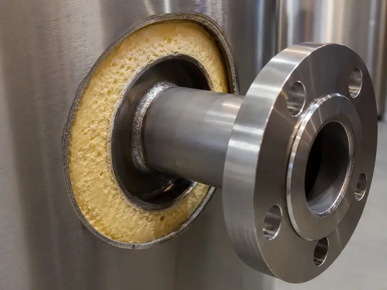
| Connections | Inlet, outlet, drain, overflow, vent, top or side manway, and optional heating coil flanges |
| Certifications and supply | CE, ISO 9001, ASME; OEM / ODM available |
All parameters are subject to project engineering review. Submit your installation environment, ambient temperature range, stored-water temperature requirement, and downstream process specification for engineering confirmation before finalizing the order.
Insulated Water Tanks: Industrial Applications
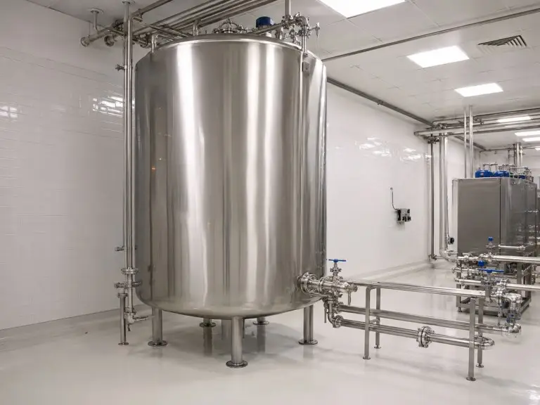
Industrial Process Water Buffer — Post-RO and Post-Softener Storage
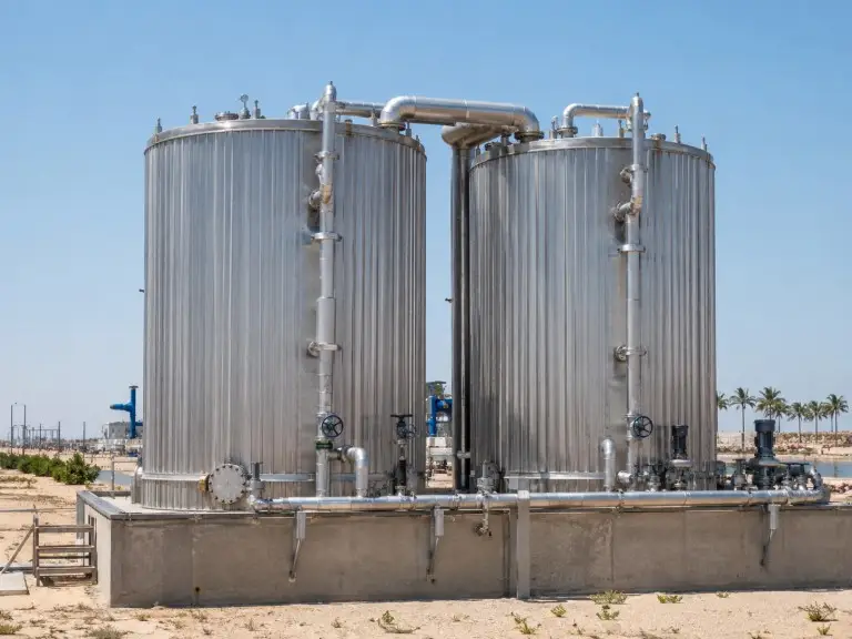
RO permeate and softened water exit the treatment stage at ambient temperature. In an outdoor installation where ambient reaches 40°C, an uninsulated storage tank absorbs heat through its shell at a rate proportional to the ΔT between stored water and surrounding air, and to the tank’s total exposed surface area. For a 10,000L cylindrical tank, that exposed surface area is substantial, so even a moderate U-value on an uninsulated shell produces measurable temperature rise within hours under high-ambient conditions.
For an illustrative engineering reference, a 5,000L post-RO permeate tank holding water at 22°C in a 40°C outdoor environment faces a ΔT of 18°C at the insulation layer continuously during daylight hours. At that differential, our engineering evaluation starts at 75mm outdoor-standard insulation, the configuration that holds stored permeate within the temperature range at which the RO membrane produced it.
A closed-cell PU foam layer rated at k ≤ 0.025 W/(m·K), sized for the site’s specific ΔT, is the engineering boundary that makes water quality consistent from treatment to point of use. Capacity in this application typically ranges from 2,000L to 20,000L or more depending on daily output volume and downstream draw rate.
Food and Beverage / Pharmaceutical Process Water Storage
Process water for food and beverage water treatment applications must hold within a defined temperature window from storage to point of use. Chemical cleaning wash water operates at defined temperatures: too cold and cleaning efficacy drops; too hot and thermal damage to food-contact surfaces or product formulation can occur. Ingredient water storage has its own temperature boundary depending on the product.
For these applications, we specify SUS316L inner shell as the baseline wherever stored water carries trace levels of chloride, which is common for coastal cities where treated municipal water commonly carries residual chloride that is aggressive in extended-contact conditions above 40°C. Insulation thickness and outer jacket material are reviewed based on the facility’s ambient conditions and whether the tank is installed in a temperature-controlled production area or an external utility corridor. Final compliance for pharmaceutical and food-grade applications must be confirmed against the applicable process specification, validation protocol, and applicable local standard.
Hotel and Commercial Building Hot Water Peak Demand Buffer
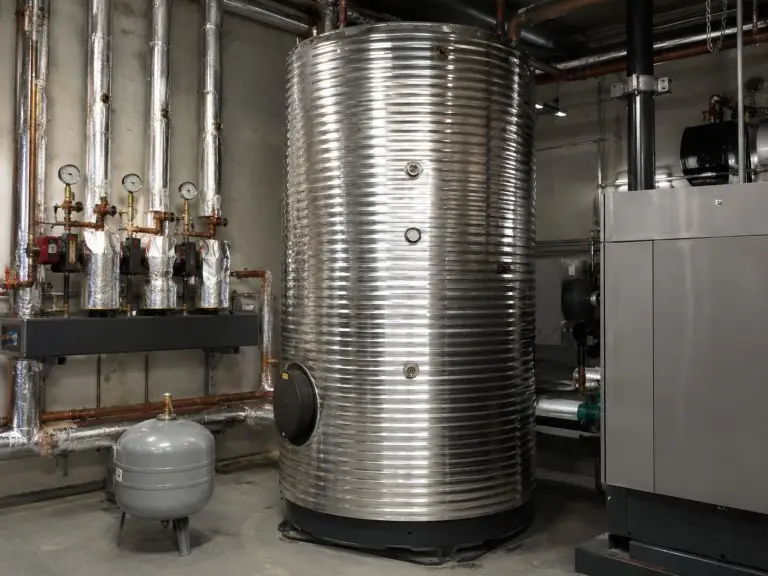
In hotels, hospitals, and large commercial buildings, hot water demand is not uniform across the day. Shower peaks, kitchen service windows, and laundry cycles create demand spikes that a heating plant cannot serve instantaneously without being over-specified for the off-peak hours. An insulated hot water buffer tank at 60–85°C absorbs the demand spike so peak-hour demand draws from stored volume rather than forcing the heating system to respond in real time.
For hotel and commercial building water treatment projects in the Middle East, Southeast Asia, and Africa, an insulated hot water buffer serves a dual purpose: retaining heat against standby loss during overnight low-demand periods, and limiting heat absorption from outdoor ambient during daytime standby when the buffer is in partial-fill mode. A 5,000L buffer tank at 70°C in a plant room where ambient reaches 42°C faces a ΔT of 28°C, so 75mm insulation is the minimum we evaluate before confirming the final specification.
HVAC Chilled Water Buffer
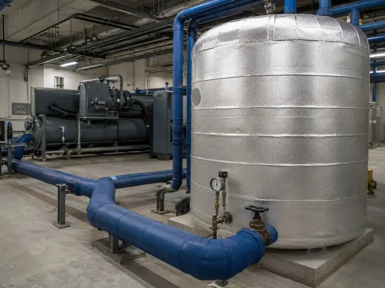
HVAC chilled water systems use buffer tanks to decouple chiller output capacity from instantaneous air handling unit demand. The buffer absorbs demand surges without triggering chiller short-cycling, reducing compressor wear and energy consumption per cooling cycle. For an insulated chilled water buffer, the engineering challenge is the inverse of hot water storage: the threat is heat gain from ambient, not heat loss to ambient.
A chilled water buffer tank in an outdoor plant room at 38°C ambient is attempting to hold water at 7°C, a ΔT of 31°C driving heat into the tank from outside. An uninsulated or under-insulated tank in this condition gains temperature faster than the chiller can replenish the cold volume, defeating the purpose of the buffer entirely. We calculate the required insulation for chilled water buffer tanks using the same U-value × surface area × ΔT framework as hot water storage, with the direction of heat flow reversed. For outdoor chilled buffer installations in high-ambient climates, 100mm insulation is a starting point for project review, not a ceiling.
Manufacturing and Certification
Qingdao, China · established 2016
Dedicated water storage and treatment equipment
Production technicians + engineers (design, QC, export)
SE Asia · Middle East · Africa · S America · C Asia
ISO 9001 + CE + ASME scope
Manufactured under an ISO 9001 quality management system with CE documentation for applicable export packages. ASME-related documentation is available for pressure vessel applications — confirm scope, working pressure, design temperature, and destination code at quotation.
OEM / ODM workflow
Custom configurations — tank geometry, connection layout, insulation specification, pressure class, and private-label supply — proceed through dimensional drawing approval before production. Available for dealers, distributors, and EPC contractors.
Complete treatment package
For buyers sourcing insulated storage as part of a complete water treatment system, we coordinate RO plant, softener, or pre-treatment equipment with correctly sized buffer storage from a single engineering review through to delivery.
Request a Project Review for Your Insulated Tank
Before we size your tank, we need to understand the thermal and operational conditions of your specific installation. Insulated tank engineering is not catalogue selection — the correct specification depends on variables that are unique to your site, your process, and your climate. Submitting the following information allows our engineering team to review your requirements and propose a specification for confirmation before we issue a quote.
- Installation environment — indoor / outdoor; covered or fully exposed to weather
- Ambient temperature range — minimum and maximum (°C) at the installation site, including seasonal extremes
- Stored water temperature — target temperature (°C) and water type (RO permeate / softened water / hot sanitary water / chilled process water / other)
- Required storage capacity — m³ or liters; daily throughput volume if available
- Working pressure — atmospheric open vent, or pressurized closed loop (MPa if known)
- Connections required — count, pipe size (DN or inch), connection type (flanged / threaded), and preferred positions (top / side / bottom)
- Downstream equipment — boiler, distribution header, HVAC hydronic loop, process line, or other
- Site constraints — space envelope, preferred orientation (vertical / horizontal), climate exposure (UV, dust, humidity, coastal salt air, frost risk)
- Project timeline and destination country — for logistics coordination and certification scope confirmation
Other Water Storage Tank Types
Insulated water tanks are one of eight storage equipment types we manufacture. Where the application does not require temperature control, the following tank types are typically specified:
Stainless Steel Water Tanks
SUS 304 and SUS 316L uninsulated vessels for potable, food-grade, RO permeate, and process water storage where temperature control is not required.
stainless steel water tanksPE Plastic Water Tanks
Rotomolded LLDPE and HDPE atmospheric tanks for raw water, brine, chemical dosing, and ambient-temperature service where metal corrosion is a risk.
pe plastic water tanksFRP Water Tanks
Glass-fibre reinforced tanks for corrosive process water, high-salinity, and large-volume outdoor industrial storage where both metal and PE are unsuitable.
frp water tanks