
Water Quality Instruments
Instruments are the diagnostic layer that makes operating boundaries enforceable: they keep dosing pumps calibrated, catch membrane fouling before failure, and verify each treatment stage. We integrate water quality instruments into complete Hiju systems and standalone monitoring packages across our water treatment parts range, matched to pipe diameter, pressure, temperature, and SCADA requirements.
Water Quality Parameters to Monitor in Industrial Water Treatment
Instrument selection starts with parameters, not with sensor models. These parameters cover the full range we configure across industrial water treatment system deliveries, and each is tied to the engineering consequence of missing continuous measurement.
0–14
RO feed, dosing, boiler feed, cooling tower. RO feed pH is controlled to the membrane model and antiscalant program — operating limits vary by membrane type, so confirm from the supplier’s datasheet. Open-loop dosing overfeeds or underfeeds as raw water chemistry changes.
−2,000 to +2,000 mV
Chlorination, dechlorination, ozone residual. ORP confirms oxidizing potential, but it is not free chlorine; ozone plus chlorine systems still need chlorine-specific sensors.
0–200 mS/cm
RO permeate, boiler feed, cooling cycles. A 250 to 600 µS/cm permeate drift over two days is the earliest real-time signal of membrane integrity loss.
0–20 MΩ·cm
Ultrapure output and semiconductor rinse. At 0.1 µS/cm, conductivity approaches its practical limit; resistivity reads 10 MΩ·cm for deionized water filtration system.
0–20 mg/L
Boiler deaeration and biological treatment. Oxygen in boiler feedwater attacks steel tube walls by pitting; optical DO reduces calibration burden in clean service.
0–4,000 NTU
Media filter outlets and RO feed SDI proxy. Outlet turbidity above 5 NTU indicates backwash before RO feed SDI rises to membrane fouling threshold.
0–20 mg/L
Disinfection and carbon outlet protection. TFC oxidative degradation begins above 0.1 mg/L free chlorine; carbon breakthrough is invisible without an inline sensor.
−10°C to 130°C
ATC input and high-temperature monitoring. A 30°C process swing distorts pH readings without ATC, and low-rated probes drift on hot deaerator lines.
SDI — Periodic Test, Not a Continuous Sensor
SDI is measured by timed filtration through a 0.45 µm pad under ASTM D4189 conditions. Standard spiral-wound RO elements typically require SDI <5, with tighter high-flux configurations often requiring SDI <3. We supply SDI test kits for periodic verification, while continuous turbidity at the same sampling point provides the real-time between-test signal. SDI is an operational fouling index, not an absolute particle-count measurement; it is most appropriate for relatively low-turbidity RO feed samples and should be interpreted alongside continuous turbidity monitoring.
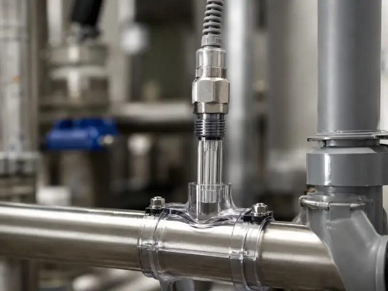
pH Engineering Detail
We monitor pH continuously at the RO feed point because thin-film composite membranes require feedwater to remain within 6.5-7.5. In chemical dosing control loops, pH is the feedback signal that determines acid or alkali injection rate.
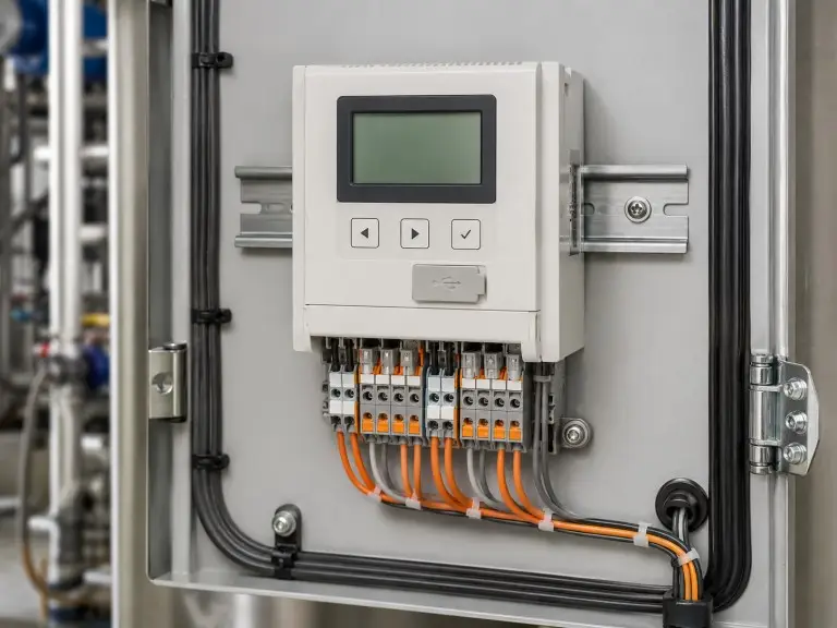
Conductivity and Toroidal Sensor Boundary
For high-fouling or high-conductivity streams above approximately 5,000 µS/cm, we specify toroidal conductivity sensors rather than contacting-electrode sensors. Toroidal sensors measure through an inductive coil with no electrodes in direct process contact, reducing cleaning cycles on cooling tower blowdown and RO concentrate.
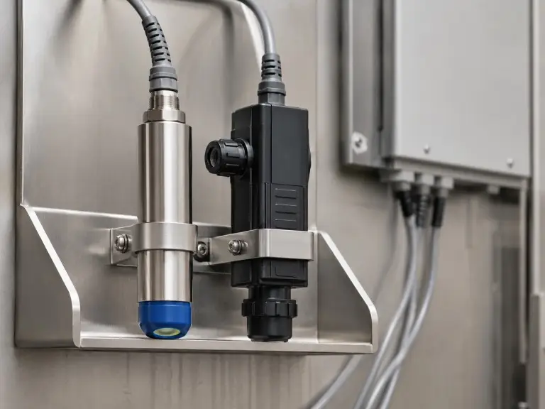
Dissolved Oxygen and Turbidity Installation Detail
Optical dissolved oxygen sensors require no polarization equilibration period and have no replaceable membrane, making them our preferred choice for boiler feedwater monitoring. Turbidity sensors belong at filter outlets as the real-time indicator of filtration performance before SDI testing confirms membrane feed suitability.
Online vs Portable vs Benchtop Water Quality Instruments
The selection between continuous inline monitoring, portable spot-check instruments, and laboratory bench units is a process control question, not a cost question.
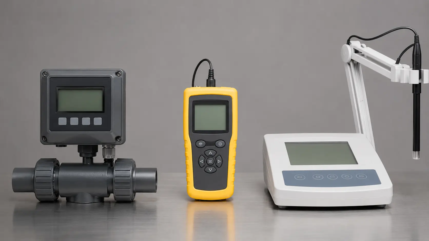
Online / Inline Instruments
We specify online analyzers for any monitoring point where a process deviation must trigger a dosing pump trim, valve command, SCADA alarm, or blowdown initiation. Output options include 4-20mA, RS485/Modbus RTU, and HART. Inline insertion probes fit DN25-DN400 pipes via threaded or flanged connections, while flow-through cells operate at 0.5-4 bar and allow sensor removal without stopping the line.
Portable / Handheld Instruments
Portable meters are correct for commissioning verification, periodic QA spot-checks, and troubleshooting. They are not substitutes for continuous inline monitoring: a meter checked once per shift creates a 7-12 hour measurement gap where membrane failure, resin exhaustion, or dosing pump failure persists undetected.
Benchtop / Laboratory Instruments
Benchtop units are for QC sample analysis, calibration standard verification, and regulatory sampling. They are not designed for vibration, dust, moisture, and temperature cycling around process pipe installations.
| Form Factor | Correct Application | Not Appropriate For | Output Signal |
|---|---|---|---|
| Online / panel-mount inline | Continuous process monitoring, control loops, SCADA | Spot-check or lab QC | 4-20mA, RS485/Modbus RTU, HART |
| Flow-through cell | Clean-to-moderate streams, 0.5-4 bar | High-solids or high-fouling streams | Per transmitter |
| Inline insertion probe | Pipe DN25-DN400, threaded or flanged | Open tank or channel | Per transmitter |
| Submersion probe | Open tank, channel, or low-flow basin | High-velocity pipe flow | Per transmitter |
| Portable / handheld | Commissioning, spot-check, troubleshooting | Continuous production monitoring | Local display only |
| Benchtop / laboratory | Lab QC, calibration reference | Process or plant-floor installation | Local display, USB/RS232 |
When Water Quality Instruments Are Not the Right Route
Water quality instruments measure conditions; they do not treat water or control chemistry by themselves. If the gap is actuation, the resolution is in control valves and dosing or blowdown architecture, not in additional sensors. If the site has no PLC, no 4-20mA input cards, no automatic dosing input, and no signal wiring plan, system design should precede instrument specification. If the application is laboratory-only sample analysis with no process pipe integration, a laboratory instrument supplier is the appropriate route.
Water Quality Monitoring Points Across RO, Boiler, and Disinfection Systems
Water quality instruments are distributed across the full treatment chain. Each measurement point protects equipment or verifies treatment output, and confirmed alarm setpoints are established during engineering review for each project.
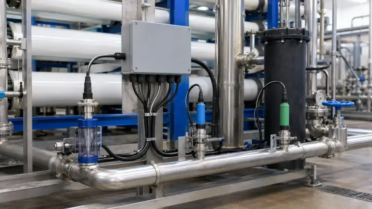
The matrix below is the framework our engineers use during system P&ID development. Each monitoring point has a pipe tapping location, flow-through cell pressure rating, sensor insertion depth, and signal cable route defined before fabrication begins.
| System | Monitoring Point | Key Parameter | Alarm / Control Trigger |
|---|---|---|---|
| RO system | Feed pre-cartridge filter | Turbidity / SDI proxy | Turbidity >5 NTU or SDI >5 indicates membrane fouling risk. |
| RO system | Feed post-carbon filter | Free residual chlorine | >0.1 mg/L means membrane exposure risk; investigate carbon bed exhaustion immediately. |
| RO system | Feed | pH | Outside 6.5-7.5 requires antiscalant and acid/base conditioning review. |
| RO system | Permeate outlet | Conductivity / TDS | Rise >15-20% above baseline indicates membrane integrity loss. |
| RO system | Concentrate | Conductivity | Elevated concentrate conductivity signals scaling risk at current recovery rate. |
| Water softener | Inlet / outlet | Hardness / Conductivity | Outlet hardness >1 gpg initiates brine regeneration cycle. |
| Ion exchange | Outlet | Conductivity / Resistivity | Rising conductivity or resistivity drop below spec means regeneration required. |
| Activated carbon filter | Outlet | Free chlorine / ORP | Chlorine breakthrough means bed exhausted and oxidant passing downstream. |
| Multi-media / quartz sand filter | Outlet | Turbidity | >1-2 NTU outlet requires backwash review. |
| Boiler feed water treatment | Feed line | Conductivity | >30 µS/cm triggers blowdown; target maintained below 20 µS/cm. |
| Boiler feedwater | Deaerator outlet | Dissolved Oxygen | DO above pressure-class alarm threshold means oxygen pitting risk. |
| Boiler feedwater | Feed | pH | Outside 8.5-9.5 requires chemical dosing review. |
| Cooling tower | Recirculating water | Conductivity | Cycles threshold exceeded opens blowdown valve; typical 1,500-4,000 µS/cm. |
| Cooling tower | Recirculating water | pH / ORP | pH 7.0-8.5 and ORP verify biocide dosing. |
| UV sterilizer | Post-UV | UV intensity | Below lamp minimum threshold requires lamp performance review. |
| Ozone system | Contact tank outlet | ORP / Ozone residual | ORP above saturation threshold reduces ozone dose to prevent carryover. |
Industrial Water Quality Instrument Specifications
The following table covers all parameter types we specify and configure for industrial water treatment installations. Calibration intervals are starting references; actual intervals are set at commissioning.
| Parameter | Measurement Range | Sensor Technology | Output Signal | Typical Installation | ATC Required | Calibration Guidance |
|---|---|---|---|---|---|---|
| pH | 0-14 | Glass electrode / ISFET | 4-20mA, RS485 | Flow-through or inline insertion | Yes | Two-point buffer; 1-4 weeks fouling, 4-8 weeks clean |
| ORP | -2,000 to +2,000 mV | Platinum or gold electrode | 4-20mA, RS485 | Flow-through or inline insertion | No | Traceable ORP standard verification |
| Conductivity contacting | 0-200 mS/cm | Two- or four-electrode cell | 4-20mA, RS485 | Flow-through, inline, submersion | Yes | KCl standard, 4-8 weeks typical |
| Conductivity toroidal | 0-2,000 mS/cm | Inductive coil | 4-20mA, RS485 | Inline pipe, high fouling | Yes | Less frequent due to no electrode exposure |
| TDS | Derived from EC | EC x 0.5-0.7 factor | Displayed with EC | Same as conductivity | Yes | Conversion factor confirmed for source water profile |
| Resistivity | 0-20 MΩ·cm | High-purity contacting cell | 4-20mA, RS485 | Ultrapure water loop | Yes | DI reference; standard industrial cells not appropriate |
| Dissolved Oxygen | 0-20 mg/L | Optical preferred; Clark cell optional | 4-20mA, RS485 | Flow-through, submersion | Temperature compensated | Optical 1-3 months clean service |
| Turbidity | 0–4,000 / 0–100 / 0–1 NTU *(0–4,000 NTU range applies attenuation/turbidimetric detection; 0–100 and 0–1 NTU sub-ranges use nephelometry)* | ISO 7027-1: nephelometric method (low turbidity) or turbidimetric/attenuation method (high turbidity) | 4-20mA, RS485 | Flow-through or submersion | No | Two-point formazin standard |
| Residual Chlorine | 0-20 mg/L | Amperometric or colorimetric | 4-20mA, RS485 | Flow-through cell | Temperature influences | Weekly to biweekly continuous service |
| Temperature | -10°C to 130°C | PT100 / PT1000 RTD | 4-20mA, RS485, direct | Inline insertion or flow-through | N/A | Verify against reference thermometer |
| SDI | 0-6 periodic test | 0.45 µm timed filtration | Manual result | RO feed sample point | N/A | ASTM D4189 protocol, interval set at commissioning |
Counterintuitive boundary: optical dissolved oxygen sensors require no polarization equilibration period and calibrate significantly less frequently than Clark cell electrochemical types.
Water Quality Instrument Specification, Configuration, and Integration
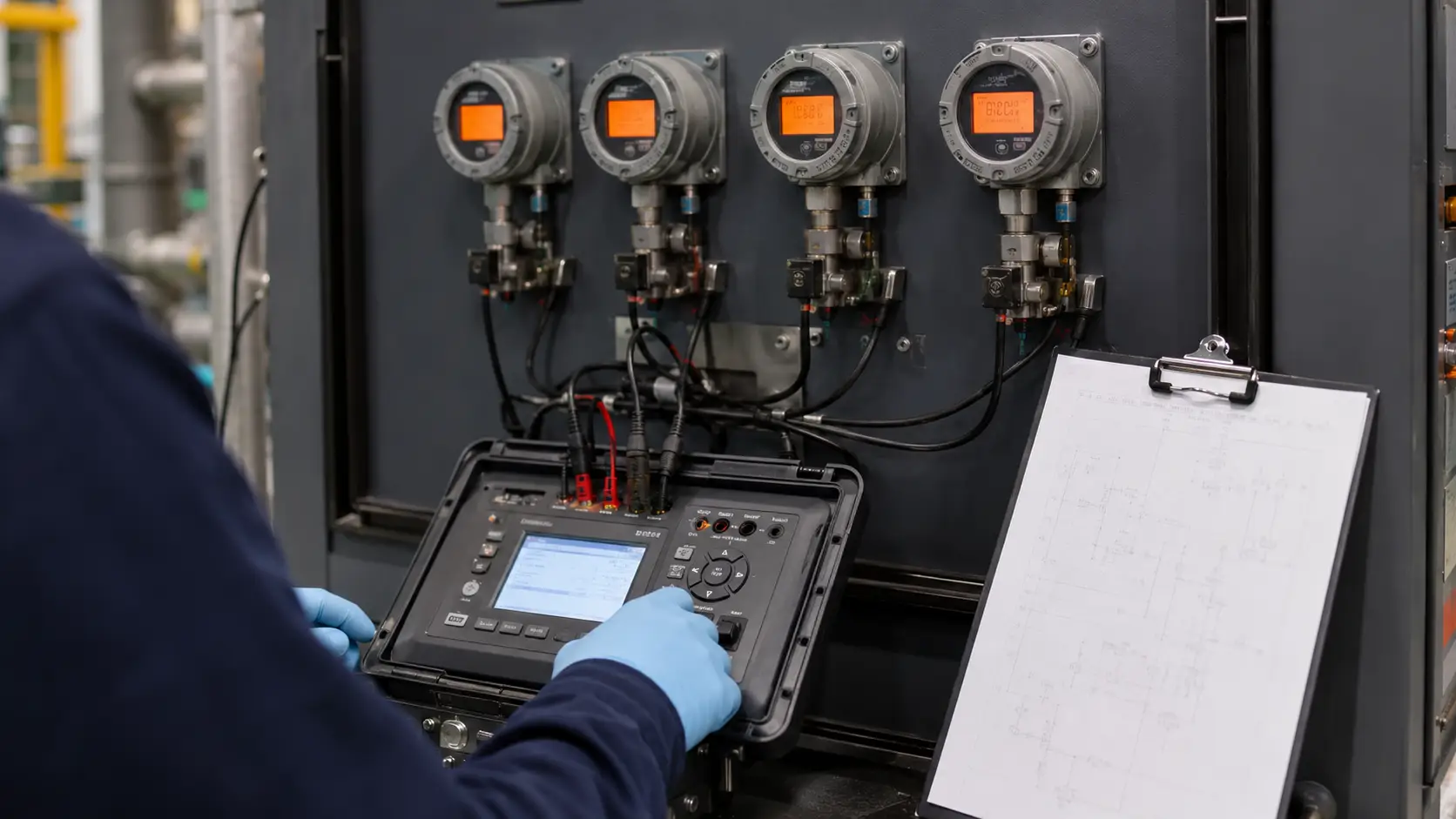
Instrument specification at Hiju begins during P&ID development, before fabrication starts and before pipe routing is finalized. Process engineers define what must be measured and at what threshold, mechanical engineers confirm pipe tapping locations and installation hardware, and electrical engineers plan signal cable routing from each sensor to the corresponding input card in the Hiju control panel.
Instruments are wired to labeled terminal blocks before the system ships. Signal designations, tag numbers, and loop descriptions are included in the as-built documentation package, so the client’s SCADA engineer works from a document aligned with physical installation. Multi-element RO skids that include membrane housings in manifold configuration include differential pressure monitoring across the array. CE documentation, ISO 9001 quality controls, and remote calibration support via WhatsApp or email are included for export markets.
Industrial RO OEM Suppliers
Packaged unit builders need sensors with confirmed output signals and transmitter settings ready to wire into their panels. Feed conductivity, permeate conductivity, and residual chlorine monitoring are standard items when we configure membrane in reverse osmosis for OEM delivery.
Power and Utilities Plants
Boiler feedwater systems need conductivity, pH, and DO monitoring specified against actual drum pressure ratings and feedwater temperature profiles, not generic alarm values.
Food and Beverage Processing
Southeast Asia and Middle East facilities require ambient temperature ratings to 40-45°C and washdown protection class confirmation as standard engineering variables.
Pharmaceutical and Laboratory Water
Resistivity monitoring at multi-pass RO and EDI output stages requires high-purity cell construction because standard industrial probes lose resolution below 0.1 µS/cm. Final compliance must be confirmed against the user’s process specification, validation protocol, and applicable local standard.
System Integrators
Complete systems arrive with instruments pre-wired to terminal blocks, loop diagrams in the documentation package, and flow or differential pressure transmitters resolved to confirmed tapping locations.
Export Market Engineers
For Southeast Asia, Middle East, Africa, South America, and Central Asia, initial calibration and sensor verification can be completed remotely with our engineers.
Common Water Quality Instrument Selection Mistakes
The most consequential decisions are often where to measure continuously, where periodic checks are acceptable, and which sensor technology is compatible with the actual stream conditions.
Not Monitoring Free Chlorine at the Carbon Filter Outlet
Polyamide TFC membranes have very limited tolerance to free chlorine; continuous exposure above the membrane supplier’s limit — commonly listed as <0.1 mg/L — can cause irreversible oxidation damage. Without a continuous inline residual chlorine sensor at the carbon outlet, breakthrough is undetectable until after membrane exposure has occurred.
Substituting Periodic Spot-Checks for Continuous Monitoring
A portable conductivity meter checked once per shift creates a 7-12 hour gap. In boiler feedwater, an 8-hour conductivity excursion deposits measurable scale; in RO, membrane failure can send off-spec permeate for an entire shift.
Using Contacting Conductivity Sensors on High-Fouling Streams
On cooling tower water, RO concentrate, or streams above 5,000 µS/cm, electrode fouling causes drift indistinguishable from a real conductivity change. Toroidal sensors are the correct specification.
Installing pH Sensors Without ATC
A 30°C intra-day temperature variation introduces apparent pH error. The dosing loop responds to temperature instead of chemistry, consuming acid or alkali while the process receives variable pH.
Skipping Insertion Depth Review
A pH sensor near the pipe wall in a DN200 line can read 0.2-0.5 pH units differently from the center-channel flow. We confirm insertion depth against pipe diameter, flow rate, and velocity profile.
Compliance & Documentation Scope
| Item | Scope |
|---|---|
| CE documentation | Available for applicable instrument packages and control panels; confirm model and destination market before order |
| ISO 9001 | Applies to quality management system, not individual instrument performance certification |
| Calibration certificate | Available for selected instruments before shipment on request |
| Loop diagram | Included for integrated skid or panel package; covers signal designation, tag numbers, and terminal block assignments |
| Factory test record | Signal simulation, wiring continuity check, alarm setpoint verification, and 4-20mA span confirmation |
| Protocol sheet | 4–20mA / RS485 / Modbus RTU / HART signal mapping supplied with as-built documentation |
Factory Loop Test — What Is Verified Before Shipment
For integrated skid and panel packages, pre-shipment verification covers: pH buffer slope check; KCl conductivity standard verification; 4-20mA signal simulation from transmitter to PLC input channel; RS485/Modbus RTU address and register confirmation; alarm setpoint verification for chlorine, turbidity, conductivity, and pH; loop diagram and calibration record included in the as-built package.
What to Include in Your Instrument Review Request
Water quality instrument selection cannot be finalized from a catalog. Send us these inputs and our engineering team will specify instruments matched to your confirmed operating variables.
- Parameters to monitor — pH, ORP, conductivity/TDS, resistivity, DO, turbidity, residual chlorine, temperature, SDI, or other.
- System type — RO, softener, ion exchange, carbon filter, multi-media filter, boiler feedwater, cooling tower, UV, ozone, or combination.
- Water source — groundwater, surface water, municipal supply, seawater, process recycle, and analysis report if available.
- Pipe diameter — nominal size and material at each proposed instrument tapping location.
- Pressure and temperature — normal and maximum operating values at each monitoring point.
- Flow rate or velocity — required for flow-through cell sizing and insertion probe depth selection.
- Output signal type — 4-20mA, RS485/Modbus RTU, HART, or Ethernet against your PLC input card.
- SCADA / PLC details — PLC or DCS model, analog channel count, protocol constraints, and fieldbus requirements.
- Ambient environment — indoor, outdoor, corrosive atmosphere, coastal salt air, or hazardous-area classification.
- Calibration capability — whether site staff can perform buffer and standard calibrations, or need pre-calibrated delivery.
- Destination country — for certification, communication standards, voltage, frequency, and documentation requirements.
- Project timeline — required instrument delivery date or system commissioning date.