
Membrane in Reverse Osmosis Systems — Industrial Element Selection and Supply
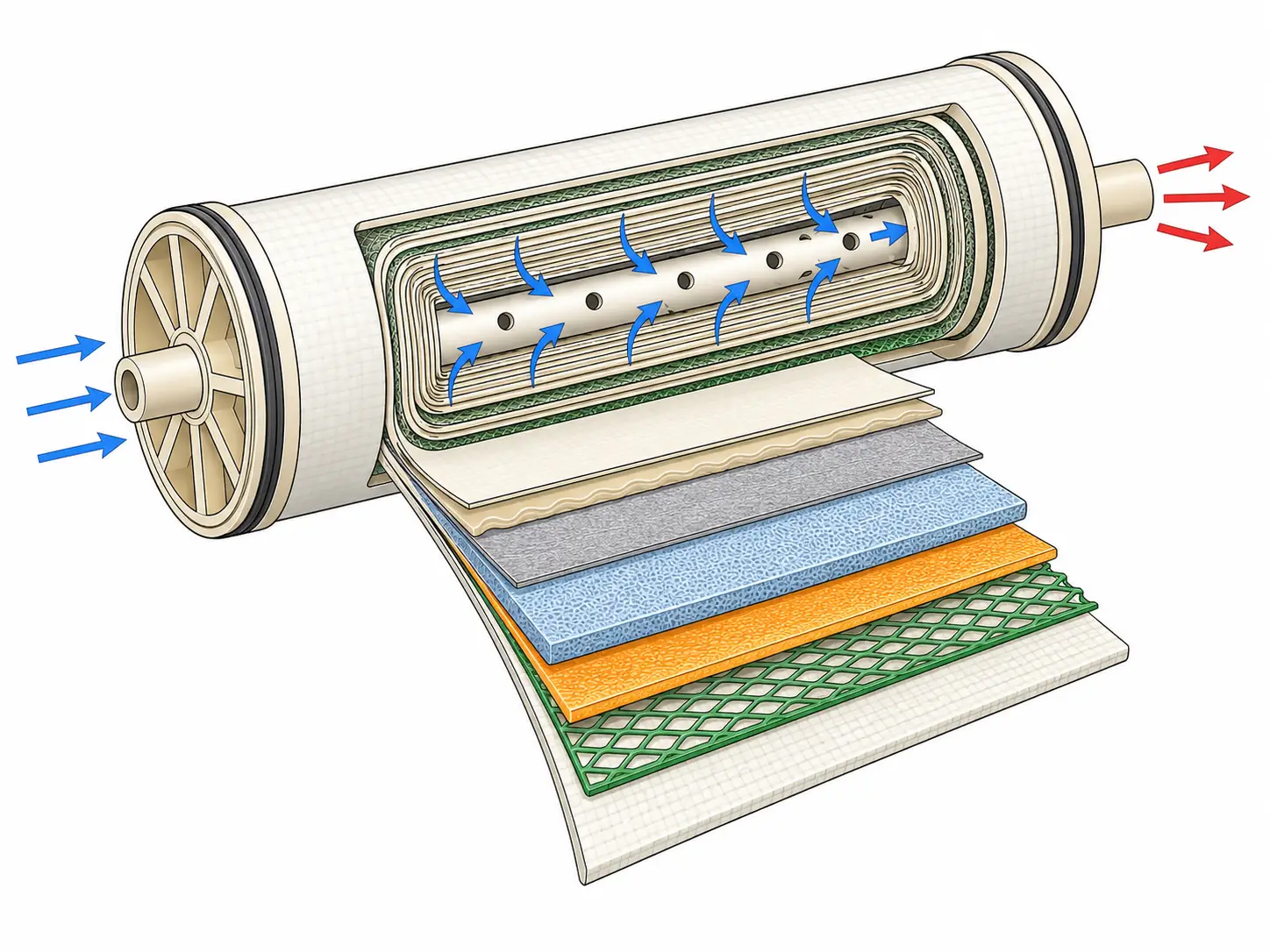
The membrane in reverse osmosis is the separation core of every pressure train — the point where applied pressure overcomes osmotic force and dissolved salts, organics, and fine particulates are rejected from the permeate stream. We supply BWRO and SWRO elements for industrial systems alongside the complete pressure-train accessory package — housing, pump, and control valve — from one engineering review.
Select Your RO Membrane Element Type, Size, and Application Class
The first selection variable is not brand — it is the feed water TDS range and the operating pressure class it demands. Choosing a membrane in reverse osmosis outside its designed TDS envelope wastes energy, accelerates membrane degradation, or fails to achieve target permeate quality. We supply RO membrane elements as part of our water treatment parts and accessories line.
| Application Class | Element Size | Feed TDS Range | Operating Pressure | Salt Rejection | Typical Application |
|---|---|---|---|---|---|
| BWRO — Low Pressure / Low Energy | 4″ x 40″ (4040), 8″ x 40″ (8040) | <500 ppm | 150-225 psi | 95-98% | Municipal tap, clean groundwater, low-TDS process water |
| BWRO — Standard Industrial | 4″ x 40″ (4040), 8″ x 40″ (8040) | 500-5,000 ppm | 225-600 psi | 97-99.5% | Brackish groundwater, industrial process return, boiler makeup water |
| SWRO — Seawater | 8″ x 40″ (8040) | 5,000-45,000+ ppm | 800-1,200 psi | 99.5-99.8% | Coastal seawater desalination, high-salinity industrial feed |
| NF — Nanofiltration (adjacent class) | 4″ x 40″, 8″ x 40″ | 500-3,000 ppm (divalent target) | 75-150 psi | ~85-97% NaCl; divalent rejection model-dependent | Hardness/sulfate removal, color removal — not full TDS reduction |
| UF — Ultrafiltration (pre-treatment, not RO) | Varies | N/A — pore-size driven, 0.02-0.05 microns | N/A | Removes suspended solids / bacteria / colloids | Pre-treatment upstream of RO; does not reject dissolved salts |
TDS boundary
If your feed TDS exceeds 10,000 ppm, a BWRO element will not stay within its operating pressure budget. Attempting to drive a BWRO element against seawater feed pushes the pump beyond design pressure without achieving target rejection — this is where SWRO-class elements begin.
UF clarification
UF membrane modules with 0.02-0.05 micron pores are not RO membranes and do not perform salt rejection. UF removes suspended solids, colloids, and bacteria upstream to reduce SDI before the RO element.
NF clarification
NF sits between RO and UF in separation energy. It is correct where calcium, magnesium, or sulfate removal at lower pressure is the objective; where low-TDS permeate is required, NF does not achieve the same outcome as BWRO or SWRO.
TFC vs. CTA: Material Selection Note
TFC (thin film composite / polyamide) is the dominant industrial choice — 95-99.8% rejection, strictly requiring free chlorine below 0.1 ppm. CTA (cellulose triacetate) tolerates moderate chlorine but carries lower rejection, about 85-93%, with a narrower pH and temperature operating range. Where chlorinated feed cannot be fully dechlorinated upstream, CTA may be appropriate; in other industrial installations, TFC is the correct choice.
Operating Condition Limits and Feed Water Requirements
Every variable in this table carries an engineering consequence when violated. These are operating boundaries per model datasheet, not general guidelines.
| Variable | Range / Limit | Consequence of Violation |
|---|---|---|
| Feed TDS | <500 ppm (low-energy BW) / 500-5,000 ppm (standard BW) / >10,000 ppm (SW) | TDS above element class design means required operating pressure exceeds pump capacity and rejection target cannot be achieved. |
| Operating pressure | 150-225 psi (low-energy BW) / 225-600 psi (standard BW) / 800-1,200 psi (SW) | Underpressure gives insufficient driving force; overpressure causes membrane compaction and irreversible flux decline. |
| Max feed temperature | 45 °C | Above 45 °C: polyamide layer hydrolysis and permanent rejection loss that CIP cannot reverse. |
| Continuous operating pH | 2-11 | Outside range: structural degradation of membrane and adhesive layers. |
| CIP cleaning pH | 1-13 (TFC-class) | Cleaning chemicals outside this range damage the element; CIP protocol must match element specification. |
| Free chlorine — TFC elements | <0.1 ppm — mandatory dechlorination | Above 0.1 ppm sustained: irreversible oxidative destruction of TFC polyamide selective layer. |
| SDI at membrane inlet | <=5 (Silt Density Index) | Above SDI 5: accelerated colloidal fouling on feed spacer, premature flux decline, shortened service life. |
| Iron in feed | <0.05 ppm (conservative pretreatment reference) | Iron deposits as oxide on the membrane surface and feed spacer, causing localized scaling. |
| Manganese in feed | <0.02 ppm | Manganese oxide deposits reduce flux and complicate CIP recovery. |
| Recovery rate | 50-85% (TDS-dependent; per model datasheet) | Recovery above design concentrates feed TDS on the tail element; scaling risk increases with concentration factor. |
| Permeate flux | 7-25 GFD (varies by water source and membrane model; refer to manufacturer datasheet) | Above design flux increases fouling accumulation; below design underproduces relative to system sizing. |
Critical: Free Chlorine and TFC Polyamide Elements
This is the most common cause of premature membrane failure in export market installations. Sustained free chlorine above 0.1 ppm attacks the polyamide selective layer through oxidation; the damage is not recoverable by CIP. Elements degraded by chlorine contact present with abnormally high salt passage and elevated permeate TDS without the flux decline or differential pressure signatures of physical fouling. Before any RO system using municipal or chlorinated surface water is commissioned, dechlorination must be confirmed and monitored continuously by ORP sensor or residual chlorine meter downstream of the dechlorination stage and upstream of the membrane inlet.
When to Replace: Reading Your System’s Performance Data
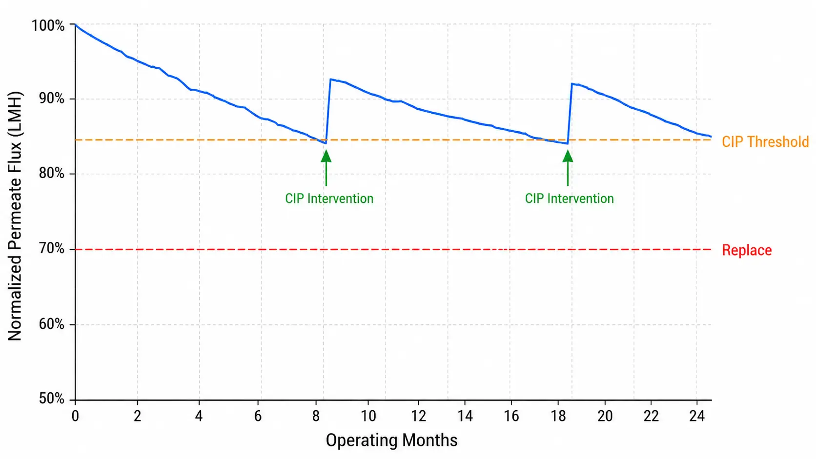
Replacement decisions should be driven by normalized performance data, not calendar time alone. Three measurable signals indicate when the membrane element is approaching end of useful service, and they map to different actions.
Normalized Permeate Flux Decline
A normalized flux decline of 10-15% below the clean baseline is the first CIP intervention threshold. If CIP does not restore normalized flux to within 90-95% of the clean baseline, the element cannot recover and should be replaced. Flux decline that deepens after multiple CIP cycles indicates irreversible fouling or membrane degradation rather than cleanable surface fouling.
Normalized Salt Passage Increase
A salt passage increase of 10% or more above baseline indicates the rejection layer is compromised. Unlike flux decline, elevated salt passage often signals that membrane integrity has already been breached by mechanical damage, chlorine exposure, or extreme pH excursion. If CIP does not reverse the trend within one or two cycles, replacement is the correct response.
Differential Pressure Increase
A differential pressure rise of 15% or more indicates feed spacer fouling or partial element blockage. Targeted CIP addressing colloidal or biological fouling can restore differential pressure in many cases. If DP remains elevated after cleaning, inspect the assembly for physical obstruction or element telescoping caused by hydraulic shock during start-up or flush cycles.
CIP Chemical Selection Must Match the Fouling Type
Low-pH CIP (pH 1.0-1.2) targets inorganic scale — CaCO₃, BaSO₄, iron and manganese deposits. High-pH CIP (pH 11.7-11.9) targets organic fouling and biofouling. Running low-pH CIP against a biofouling problem produces incomplete recovery and misleading post-CIP data. If all three normalized parameters return to within 90-95% of baseline after CIP, the element is serviceable. If any parameter remains outside that threshold after one or two CIP cycles, replace the element.
Industry reference: industrial RO membrane elements typically deliver 3-5 years of service under properly maintained conditions with adequate pre-treatment. Under high-fouling conditions or inadequate pre-treatment, service life can compress to as little as 18 months.
Pre-Treatment Boundary: What Must Be Upstream of the Membrane
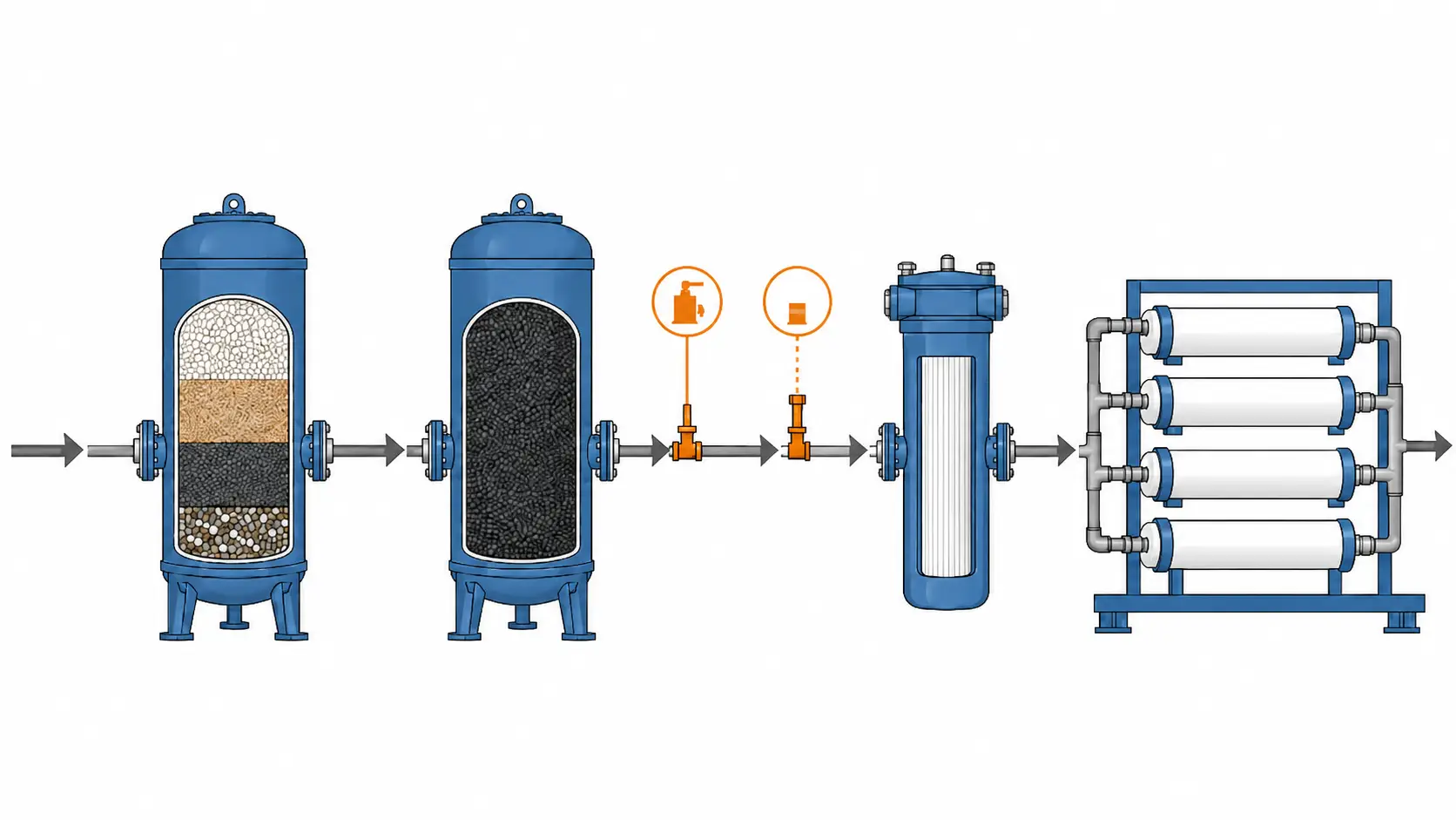
Every membrane in reverse osmosis requires controlled feed water. The pre-treatment train is not optional — it is the technical boundary that determines whether the membrane element operates within its design envelope or fouls ahead of schedule.
Feed Water SDI ≤ 5
The Silt Density Index measures the colloidal particle load in the feed stream. Feed water above SDI 5 rapidly fouls the feed spacer and membrane surface. SDI is controlled by multimedia filtration and 5-micron cartridge filtration; high-turbidity sources may use upstream ultrafiltration to reduce SDI below 2.
Free Chlorine < 0.1 ppm
Municipal and chlorinated industrial water sources must be dechlorinated upstream of the membrane. Activated carbon filtration is standard; sodium bisulfite dosing is used where carbon contact time is insufficient. Continuous residual monitoring downstream of dechlorination is recommended because spot testing does not protect TFC elements between checks.
Iron < 0.05 ppm / Manganese < 0.02 ppm
Well water and groundwater sources commonly exceed both limits. Iron and manganese co-precipitate as oxides on the membrane surface and feed spacer, causing localized scaling that CIP cannot fully remove once deposits are established. An iron and manganese removal filter is required upstream for feed water exceeding these values.
Antiscalant When Concentrate LSI > 0
When concentrate LSI exceeds zero at design recovery, CaCO₃ scale forms on the membrane surface, most severely on the final element in each pressure vessel. Antiscalant selection depends on concentrate chemistry and the scaling ion composition, not only the raw-water TDS value.
Without proper SDI control, chlorine removal, and antiscalant dosing, fouling rates increase, CIP frequency rises from quarterly to monthly, and membrane service life compresses from the 3-5 year reference to as low as 18 months. The total membrane replacement cost over a 10-year system life under inadequate pre-treatment is substantially higher than the capital cost of a correctly sized pre-treatment train.
Common Mistakes That Shorten Membrane Element Service Life
The following operational scenarios are the most common causes of premature membrane element failure or early-replacement cycles among the industrial RO systems we supply in export markets.
BWRO Elements on Seasonally Rising Feed TDS
BWRO systems sized to average TDS encounter adverse conditions when groundwater TDS rises seasonally toward 5,000 ppm. As TDS increases, recovery declines and operating pressure required to maintain permeate flow increases. If the pump was sized to lower seasonal TDS, the element is starved of driving force and normalized flux decline is misread as fouling.
Annual feed water analysis and performance trending are the correct management tools — not CIP on an element that is structurally underpressured.
Dechlorination Failure on Municipal Supply
An exhausted activated carbon filter passes residual free chlorine to the TFC element at concentrations that cause irreversible oxidative damage to the polyamide selective layer. The failure signature — elevated salt passage without corresponding flux decline — is often misattributed to a leaking O-ring or damaged brine seal.
Continuous ORP monitoring downstream of the dechlorination stage is the correct mitigation; periodic spot testing does not detect gradual carbon exhaustion.
Replacing 4040 with 8040 Without Housing Change
A 4-inch-ID housing cannot accommodate an 8040 element. Even where an element physically enters the wrong housing, the O-ring brine seal is absent and feed water bypasses the rejection layer entirely. The system then produces high-volume permeate at near-feed TDS with no measurable flux decline or differential pressure change.
Element size changes require matched housing replacement. We confirm element format against housing specification before shipping any replacement order.
Omitting Antiscalant at Positive LSI Recovery
At 60-70% recovery, even marginally positive LSI concentrates above CaCO₃ saturation on the final element in each vessel. Calcium carbonate scale that nucleates deeply in the tail-element feed spacer is poorly recovered by low-pH CIP alone and causes permanent differential pressure and rejection degradation.
Omitting antiscalant to reduce chemical cost is a preventable cause of tail-element failure in the systems we review for export market customers.
System-Level Data Without Element Trending
Operators who measure only system-level permeate TDS and total flow may miss early fouling or mechanical damage in individual elements. In a multi-element pressure vessel, the lead element sees fresh feed and the highest driving force; the tail element sees concentrated reject at the lowest driving force. SDI-driven colloidal fouling appears first on the lead element, while scaling tends to appear first on the tail element.
System-level normalized data can mask deterioration until aggregate output changes, when multiple elements may need replacement rather than one.
Element, Housing, Pump, and Valve: The Complete Pressure Train
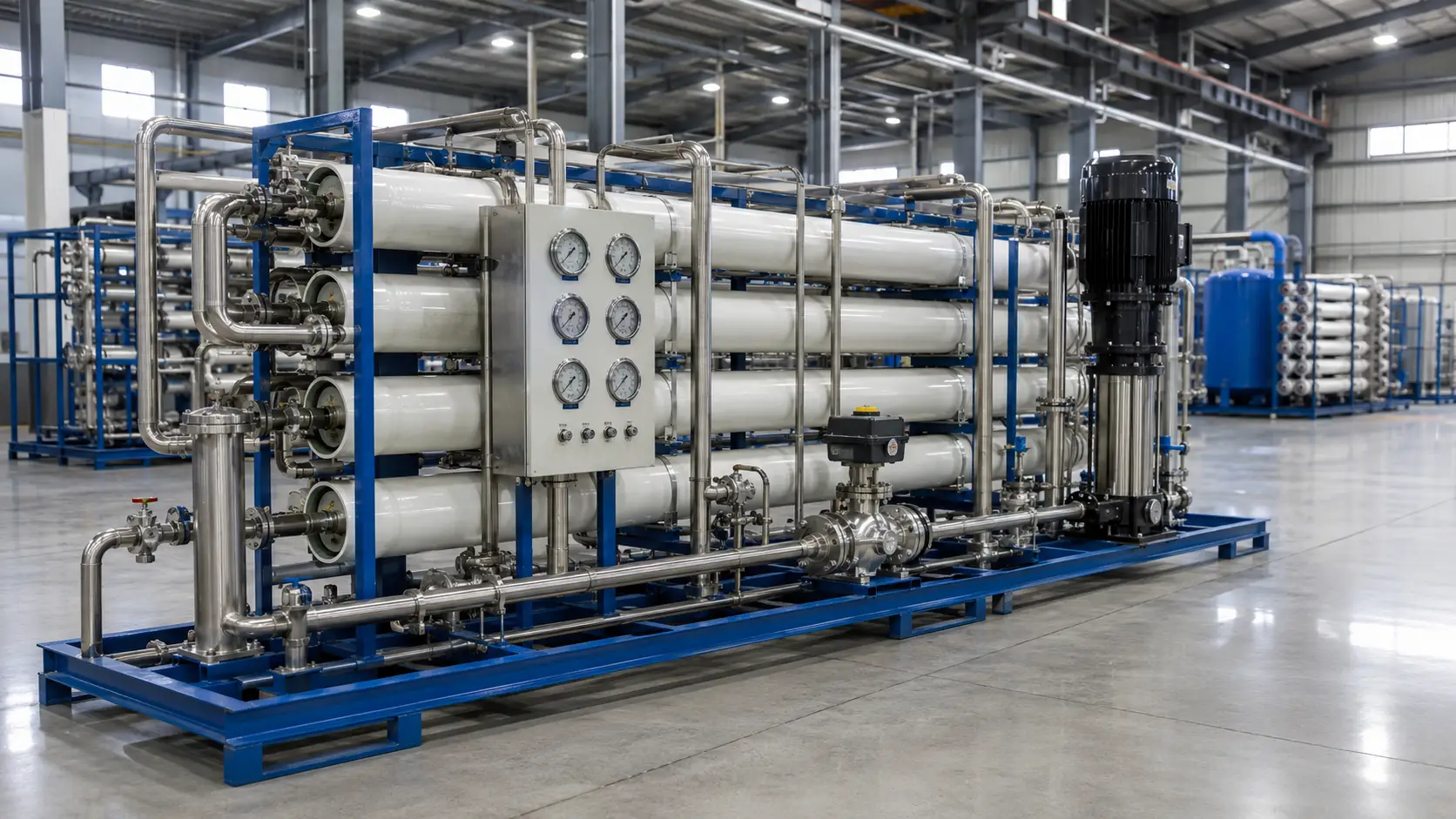
The membrane element does not operate in isolation. Its size, application class, and recovery target directly determine the specification of every other component in the RO pressure train — and those components must be matched, not estimated.
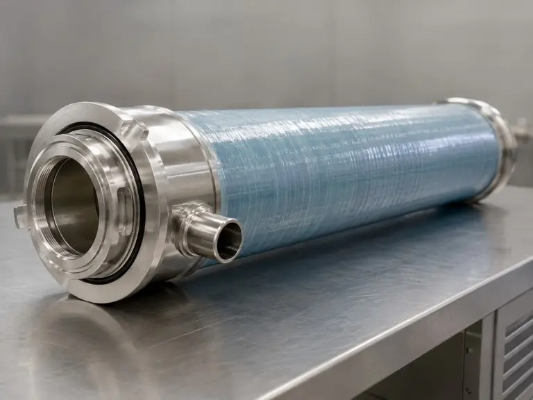
Element → Housing Inner Diameter
A 4040 element requires a 4-inch ID pressure vessel; an 8040 element requires an 8-inch ID vessel. A tolerance mismatch of even a few millimetres defeats the O-ring brine seal and allows feed bypass into the permeate channel.
Membrane housings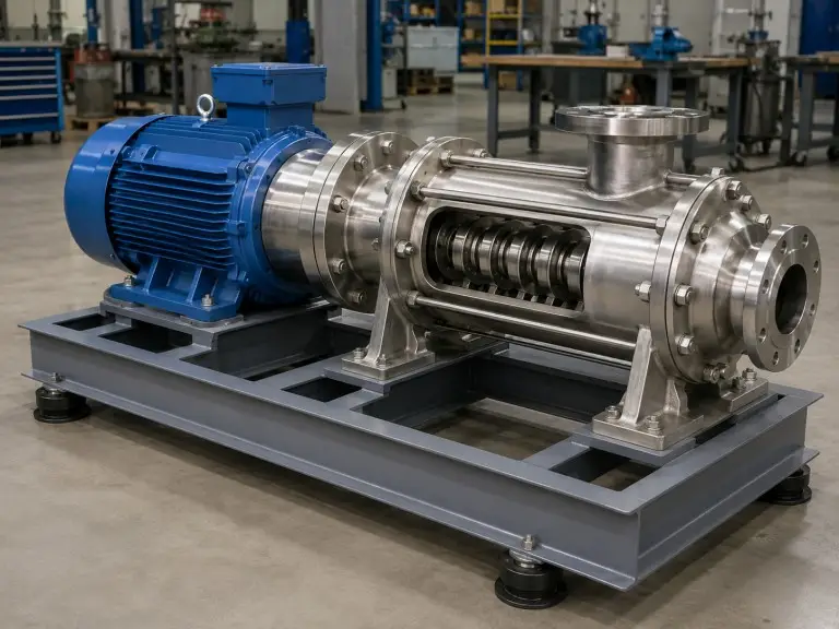
Application Class → Pump Pressure
BWRO standard elements operate at 225-600 psi; SWRO elements require 800-1,200 psi at the pump outlet. A BWRO pump cannot deliver seawater-class pressure without motor and impeller redesign.
Pumps for RO systems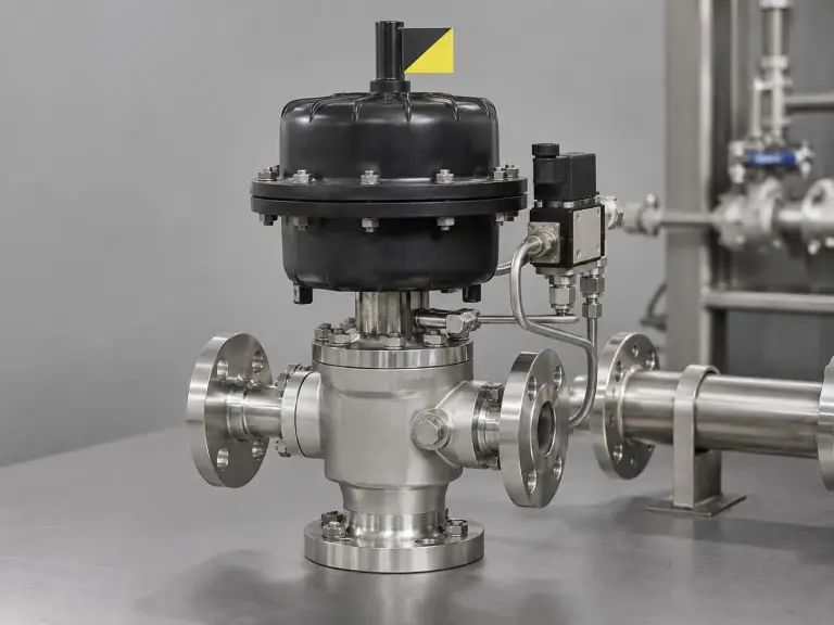
Recovery Rate → Valve Configuration
BWRO: 50-75% recovery; SWRO: 35-45% recovery. Recovery above design raises concentration factor on the final element, increases differential pressure, and accelerates scaling. Concentrate and flush valves must hold recovery inside the design window.
Control valvesWe supply all three components — housing, pump, and valve — alongside the membrane element. Consolidating the full replacement-part package from one engineering review eliminates dimensional compatibility risk and simplifies procurement coordination for buyers in export markets.
Industrial Applications: Where RO Membrane Elements Are Specified
The following applications represent the primary industrial contexts where BWRO and SWRO membrane elements are specified as the separation stage. Each has distinct feed water conditions and permeate quality requirements — confirm your application category before element selection.
Boiler Feed Water Demineralization
Power plants and industrial steam systems require permeate TDS in low single-digit mg/L; some high-pressure boiler specifications call for below 1 ppm, requiring high-rejection TFC elements and downstream mixed-bed polishing. Pretreatment must address bicarbonate, silica, and iron carryover. See our boiler feed water treatment solution for full system design.
Pharmaceutical and Electronics Ultra-Pure Water
High-purity processes use RO membranes before downstream polishing resin beds and UV treatment. Endotoxin, TOC, and microbial count constraints must be reviewed at system design stage and are not solved by element selection alone. Our deionized water filtration system page covers full system scope.
General Industrial Process Water
Manufacturing lines using municipal or brackish groundwater specify BWRO standard elements in 4040 or 8040 format. Feed TDS of 500-3,000 ppm and 225-400 psi is typical for cooling tower makeup, rinsing, surface treatment, and general production water.
Brackish Groundwater for Industrial Sites
Industrial facilities without reliable municipal supply draw from wells where TDS often sits in the 1,000-5,000 ppm range. Iron and manganese must be confirmed and treated upstream; feeds above 0.05 ppm iron foul BWRO elements rapidly without adequate removal.
Seawater Desalination for Coastal Facilities
SWRO elements operate against seawater TDS at high pressure. At this class, energy recovery, pump efficiency, and vessel pressure ratings become design-critical variables reviewed alongside element selection.
Full System Design
Complete system design for boiler feed water, pharmaceutical ultra-pure water, and other application-specific configurations — including pre-treatment, system skid, and controls specification — is handled through our water treatment solutions pages.
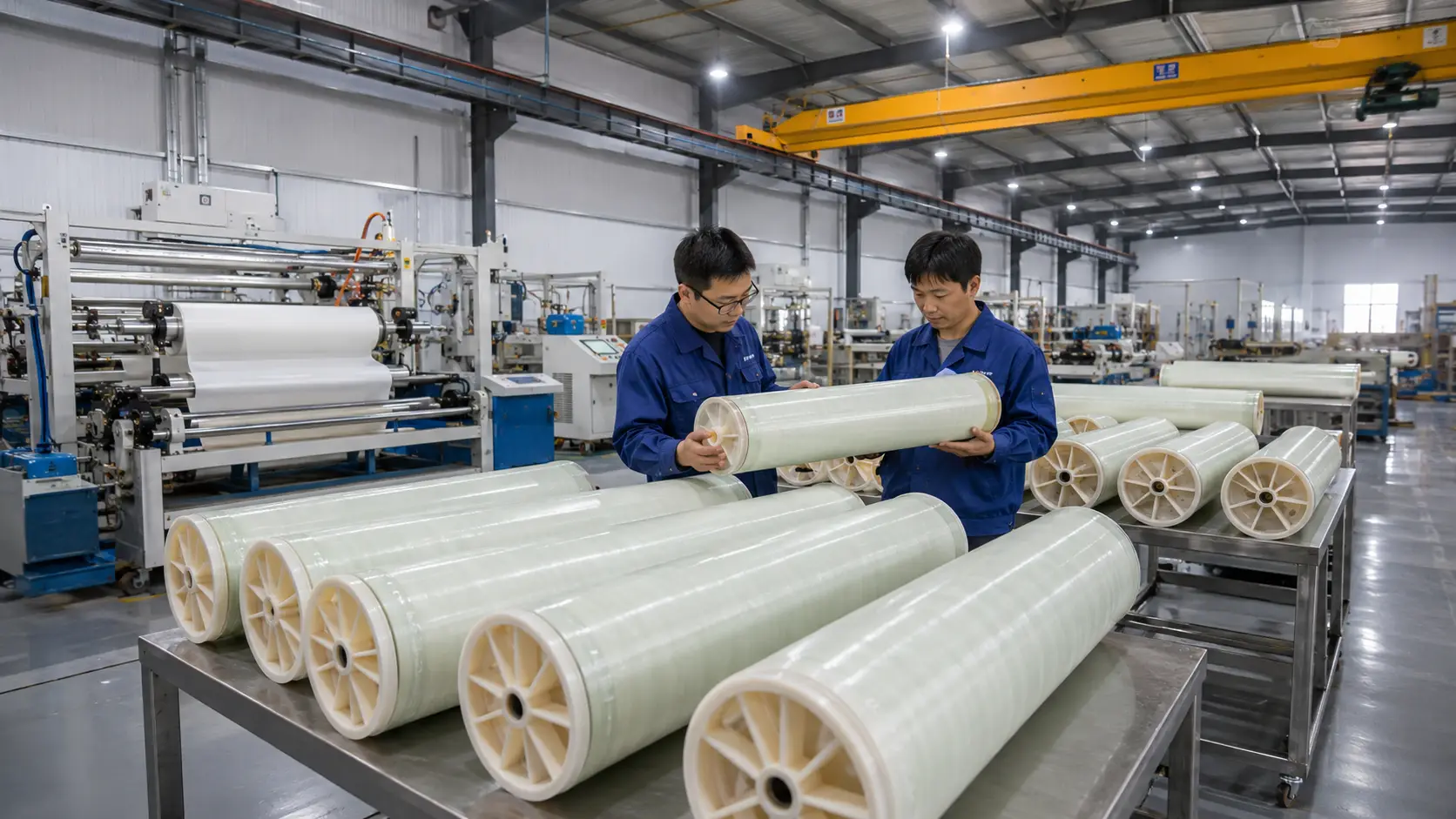
Factory-Built Elements With Engineering Review
Our membrane elements are produced at our Qingdao facility under CE and ISO 9001 quality frameworks, with OEM supply available for system integrators in export markets.
Engineering Review
Every project receives feed-water-based element selection, recovery target review, and pre-treatment scope confirmation before shipment.
OEM Element Supply
Custom labeling, specification-matched construction, and volume supply arrangements for system builders who manufacture their own branded RO systems.
Export Documentation
CE certification and ISO 9001 quality-system records as standard documentation; specific test reports or third-party inspection documentation arranged per project.
Element Specification Inputs
Feed-water data and existing-system context determine which element class, size, and format we recommend.
- Feed water TDS — mg/L or ppm; seasonal variation if known
- Water source type — municipal, brackish groundwater, seawater, surface water, industrial return
- Feed temperature range — at the membrane inlet, min/max
- Target permeate TDS or quality specification — process or regulatory target
- Operating pressure available — from existing pump or designed pressure budget
- For replacements: current element format (4040 / 8040), elements per vessel, current brand / model
- Application category — boiler feed, ultra-pure, process water, brackish, seawater