
Multi-Tank Water Softener Systems — Triplex to Custom Multi-Bank Arrays
When a duplex configuration reaches its flow ceiling — or your operation runs around the clock with no regeneration window available — adding a third vessel changes the entire engineering equation. We build multi tank water softener systems from three to six or more resin vessels as a single factory-tested skid, with shared service headers, PLC-based rotation control, and coordinated brine handling.
For flow rates below 50 GPM with a scheduled regeneration window, our water softener systems family includes simpler configurations at lower capital cost.
Which Configuration Tier Matches Your Flow and Operating Schedule
Use this table to identify whether your flow rate, operating schedule, and demand profile put you in the single-tank, duplex, or multi-tank tier before reviewing the sections below.
| Configuration Tier | Typical Peak Flow | Regeneration Window Requirement | Demand Profile | Configuration |
|---|---|---|---|---|
| Single-tank | Below ~30 GPM | Planned offline window acceptable (daily or scheduled) | Consistent, low-volume demand | Single valve single tank |
| Duplex alternating | 30–100 GPM (project-specific) | Overnight window available; both tanks complete rotation without service gap | Moderate demand; predictable daily schedule | Single valve double tank (alternating) |
| Duplex parallel | 50–150+ GPM | Short window acceptable; parallel service covers peak; one vessel regenerates while other holds full flow | High peak demand; some regeneration flexibility | Double valve double tank (parallel) |
| Multi-tank (3+ vessels) | Above duplex parallel service ceiling; or any flow rate with no acceptable regeneration gap | No acceptable regeneration window; 20+ hours/day continuous demand | Continuous high demand; wide peak-to-average ratio causing channeling risk in fixed large-tank | This page |
If your peak demand is above 150 GPM and no regeneration window exists, multi-tank is the minimum viable configuration. If your demand varies sharply between peak and off-peak periods and an oversized single tank would channel during low-flow hours, progressive multi-tank is the correct variant within this tier.
Three Conditions That Make Multi-Tank the Engineered Answer
Before we specify a multi tank water softener array, we assess three conditions in the initial project review. When at least two of the following apply, multi-tank is the correct configuration tier.
Peak Flow Exceeds Duplex Parallel Capacity
When peak demand exceeds the combined service GPM of two tanks at their designed service velocity — typically 3.5 to 5 GPM/ft³ as a design reference — a third vessel is the correct resolution. Increasing vessel diameter introduces channeling risk during low-flow periods.
No Acceptable Regeneration Window
In operations running 20+ hours per day with high variable demand — pharmaceutical cleaning lines, food-grade rinse circuits, continuous boiler feed — there is no safe gap for a two-tank system. A triplex keeps two tanks in service at all times while the third regenerates.
Demand Variation Causes Channeling
A large single vessel requires approximately 6 GPM minimum as a design reference to maintain even bed contact. Below that, water channels through the resin and hardness leakage rises. Progressive multi-tank resolves this by operating smaller vessels each at or above minimum design flow velocity.
Decision threshold
When at least two of the three conditions above apply simultaneously, multi-tank is the minimum viable configuration tier. If only one applies, we review whether a duplex parallel system can cover the requirement before committing to a third vessel.
When Multi-Tank Is Not the Right Choice
We flag the following conditions in the initial review as grounds for recommending a simpler configuration rather than multi-tank. This is about matching system complexity to actual operating requirements.
Peak Demand Consistently Below 50 GPM with a Predictable Overnight Window
A single valve double tank water softener handles this cleanly. The capital, control system complexity, and footprint cost of a third vessel are not justified for demand profiles at this level.
The Application Tolerates Occasional Hardness Breakthrough Above 3 ppm
Utility-grade softening at lower service velocities does not require the rotation depth of a triplex. Over-specifying output quality drives unnecessary capital cost into brine and resin volume.
Feed Water Iron Around or Above 0.3 mg/L, Suspended Solids Above 15 NTU, or Free Chlorine Above 1 mg/L Without Upstream Pretreatment
These conditions foul ion exchange resin regardless of tank count. Multi-tank does not resolve a pretreatment deficiency — it multiplies the fouling problem across more vessels and multiplies the resin replacement cost. We confirm upstream treatment before finalizing any softener configuration tier.
Space Constraints Make a Three-Tank Skid Footprint Physically Impossible
A triplex skid with 48″ diameter vessels occupies roughly 16′ × 8′ at minimum on a prepared pad, not counting brine system clearance. When a two-tank footprint is the hard constraint, a double valve double tank water softener can approach comparable peak flow rates within a smaller area — provided the two-vessel service ceiling is sufficient for the actual demand.
Four Configuration Variants Within the Multi-Tank Softener Family
Multi-tank systems are not a single product. We produce four configuration variants; the correct selection depends on your service flow profile, regeneration frequency, available footprint, and downstream application tolerance.
| Configuration | Vessels in Service | Vessels Regenerating | Typical System Flow | Primary Fit Condition |
|---|---|---|---|---|
| Triplex alternating | 2 | 1 | 100–300 GPM (project-specific) | 24/7 demand; no acceptable regeneration interruption; moderate peak-to-average ratio |
| Quadruplex | 3 | 1 (or 2+2 split) | 200–500+ GPM | Extreme continuous demand; pharmaceutical or power generation with redundancy requirement; final compliance per applicable standard |
| Progressive multi-tank | 1–4 active (demand-matched) | 1+ cycling | 10–300+ GPM (variable demand) | Wide peak-to-average ratio; salt and water efficiency is a priority; channeling risk in oversized single-tank |
| Custom multi-bank | 3–6+ | 1–2 | Project-engineered | OEM skid integration; EPC project specification; volume or footprint constraints |
For projects where a single vessel with a scheduled offline window is sufficient, a single valve single tank water softener covers applications below approximately 30 GPM with acceptable regeneration downtime — this is the entry point of the softener family, not the multi-tank tier.
How a Triplex System Rotates Without Interrupting Service Flow
The rotation cycle is the defining engineering feature of a multi tank water softener. The precise sequence of which vessel is doing what — and what prevents a service gap during the transition — is the technical question we address here.
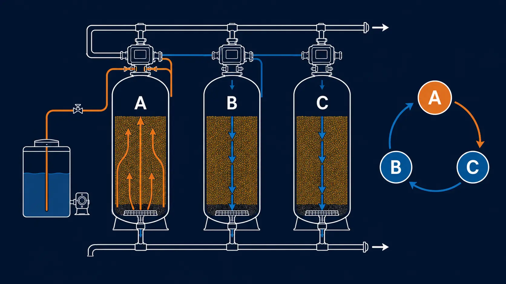
Initial Service State
Tank A and Tank B are both in service. The common header draws from both vessels at full design flow. Tank C holds in standby after completing its most recent regeneration.
Rotation Trigger
When the PLC registers that Tank A has reached its grain exhaustion threshold — calculated from cumulative metered throughput and source hardness — it initiates Tank A’s regeneration. Tank C enters service alongside Tank B.
Regeneration Cycle
Tank A proceeds through backwash (8–15 min), brine draw (30–60 min), slow rinse (20–30 min), and fast rinse (10–15 min). Total cycle: 90–120 minutes. Tank B and Tank C sustain full service flow throughout.
Return to Service
When Tank A’s rinse effluent meets the hardness confirmation threshold, it re-enters service. The PLC queues Tank B for the next rotation based on its own meter reading.
Brine system coordination
The brine tank is shared across all vessels and sized to support regeneration frequency without manual refill between cycles. The PLC monitors brine level independently from the rotation scheduler.
Control system
Rotation sequencing runs through a PLC with HMI display. SCADA integration and remote monitoring are available. In progressive mode, the PLC also manages which vessels are active based on real-time flow rate. Service vessel count never drops below two, provided two service vessels are sized to carry the required design flow.
System Components on a Factory-Assembled Multi-Tank Skid
We factory-assemble each multi tank water softener skid as a single tested unit — common headers, valve manifolds, PLC harness, and brine connections are pre-piped and pre-wired before shipment. The standard triplex skid assembly includes the following components.
Common Inlet Header
Single inlet connection branches to all three vessels with individual isolation valves and flow measurement points for per-vessel monitoring.
Resin Vessels
FRP tanks (14″–63″ diameter) for standard temperature and pressure applications, or custom carbon steel vessels for high-temperature service or when ASME-stamped vessel configurations are specified by the project engineer. Each vessel contains ion exchange resin loaded to design volume.
Valve Nest Per Vessel
Multiport control valve or individual valve set covering service, backwash, brine draw, slow rinse, fast rinse, and reject positions. Each valve is wired directly to a dedicated PLC output — the controller confirms valve position before advancing the regeneration stage, preventing a partial-position fault from advancing to brine draw with an incorrectly seated valve.
Common Service Outlet Header
Collects treated water from all vessels in the service position; single outlet to the downstream application.
Brine System
Bulk brine silo or brine tank with brine pump, educator, and level controls, sized for continuous multi-vessel rotation. Brine draw volume per vessel and total daily salt demand are calculated before selecting silo capacity, so the system can complete a full rotation sequence without a manual refill event during a peak operating day.
PLC Controller with HMI
Monitors per-vessel throughput, regeneration stage progress, brine system status, and alarm conditions. Rotation sequencing is fully automatic.
Bypass Manifold
Allows individual vessel isolation for inspection or maintenance without interrupting service flow through remaining vessels.
Skid Frame
Carbon steel or stainless steel skid base, fully factory-assembled, pre-piped, pre-wired, and factory-tested prior to shipment. Single-lift installation on a prepared concrete pad.
Inlet and outlet connections range from 1.5″ NPT to 12″ flanged, sized to the system’s design service flow rate during the engineering review — not a catalog default.
Operating Parameters and Design Ranges for Multi-Tank Systems
All values are design operating ranges. Final specifications are project-configured based on confirmed source water analysis, flow profile, and downstream application requirements.
| Parameter | Operating Range | Engineering Notes |
|---|---|---|
| Number of vessels | 3–6+ | Triplex (3) standard; quadruplex (4) for extreme continuous demand; custom multi-bank (5–6+) for OEM integration |
| Individual vessel diameter | 14″–63″ FRP; up to 96″+ steel | Diameter selected for target service velocity — not automatically maximized |
| Individual grain capacity per vessel | 90,000–1,500,000+ grains | Higher grain capacity extends cycle time; must balance against service velocity constraint |
| Total system service flow | 50–500+ GPM | Sum of simultaneous service vessels at target service velocity; project-engineered |
| Minimum flow (progressive mode) | Minimum flow is confirmed by vessel diameter, resin volume, and distributor design | Not quoted as a universal value; prevents channeling at variable-demand sites |
| Recommended service velocity | 2–5 GPM/ft³ resin | 2 GPM/ft³ for superior output (<0.15 grain/gal leakage); 3.5–5 GPM/ft³ for standard commercial output |
| Operating pressure | 50–150 psi inlet; 100 psi system recommended | FRP vessel rated to 150 psi; steel vessel ratings project-specific |
| Operating temperature | Up to 60°C / 140°F (FRP vessels) | Temperature limit is confirmed by vessel rating, resin grade, valve seals, distributor material, and piping material. Higher temperature requires steel vessel specification |
| Output hardness | Outlet hardness is project-configured in mg/L as CaCO₃ | Depends on inlet hardness, service velocity, resin volume, salt dose, and regeneration mode. Not quoted as a universal guarantee |
| Iron co-removal | Iron review trigger: iron around or above 0.3 mg/L requires upstream pretreatment review. Higher concentrations require oxidation/filtration before ion exchange softening | Confirmed from water analysis |
| Resin volume per vessel | 3–119+ ft³ | Sized to grain capacity requirement and vessel diameter |
| Regeneration trigger | Meter-based (demand-initiated) recommended; timer-based available | Meter-based eliminates unnecessary regeneration cycles; recommended for variable demand |
| Regeneration duration per vessel | ~90–120 minutes | Four-stage sequence: backwash, brine draw, slow rinse, fast rinse |
| Salt dose per regeneration | 25–160 lb per vessel | Varies with resin volume, target output hardness, and brine concentration |
| Brine concentration | 6–15 lb NaCl per 1,000 grains removed | Higher concentration for tighter output hardness targets |
| Inlet/outlet connections | 1.5″ NPT to 12″ flanged | Sized to system flow rate during engineering review |
| Control system | PLC + HMI standard; SCADA-ready optional | Per-vessel monitoring, rotation sequencing, alarm management |
| Vessel certifications | Documentation scope: CE-related documents and ASME-stamped vessel options confirmed by selected vessel type, pressure rating, and project requirements | ISO 9001 covers manufacturing process across all configurations — ASME is not a default for all vessel types |
| Skid mounting | Fully factory-assembled, pre-piped, pre-wired, factory-tested | Single-lift installation on prepared pad |
| OEM/ODM | Available | Custom valve configuration, control system branding, private label |
Where Multi-Tank Softening Is Specified by Application
Multi-tank systems are specified where a duplex configuration creates a structural trade-off — in flow capacity, regeneration scheduling, or output consistency — that the application cannot accept.
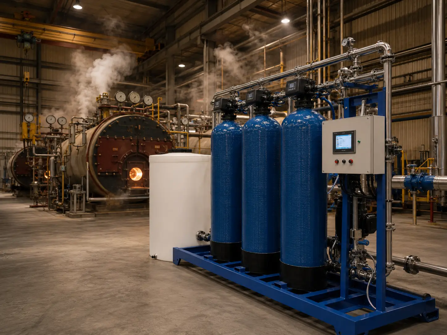
Large Boiler Feed Water Systems
Industrial boiler complexes at 200+ GPM with continuous 24/7 demand have no viable regeneration window in a two-tank configuration. Hardness above 0.5 ppm risks scale on heat exchange surfaces. For our boiler feed water treatment projects, a triplex is typically the configuration when feed rates exceed 150 GPM.
Food and Beverage Process Water
CIP circuits and food-grade rinse lines require simultaneous high flow and consistent outlet hardness — typically ≤1 ppm. When a cleaning sequence demands 150+ GPM at sub-1 ppm hardness, a duplex system cannot sustain that output through a full cleaning cycle.
Pharmaceutical Purified Water Pretreatment
Purified water pretreatment lines require consistent hardness below 0.5 ppm to protect RO membranes. A triplex keeps service vessel count at two at all times, so outlet quality does not vary during regeneration. Final compliance must be confirmed against the user’s process specification, validation protocol, and applicable local standard.
Large Hotel and Commercial Complex
Multi-building estates and campuses have demand that varies sharply between peak and off-peak. Progressive multi-tank prevents channeling by keeping each vessel at or above minimum design flow velocity. For our water filtration systems for commercial use projects, this applies to complexes above 500 rooms.
Industrial Laundry and Textile
Commercial laundry at 100–200 GPM requires continuous soft water without scheduling around regeneration. Triplex with meter-based demand-initiated regeneration is the standard fit for high-volume predictable demand.
Cooling Tower and District Cooling
Large cooling towers and district cooling require continuous make-up softening. Make-up rates frequently exceed 200 GPM during summer peaks. A triplex keeps two vessels in service at all times.
Six Specification Errors to Review Before Confirming Tank Count
Before confirming a multi-tank configuration, our engineering review checks the following conditions — because each of these, if unaddressed, drives either unnecessary cost or a system that underperforms in service.
Specifying Triplex for a Site That Has an Overnight Regeneration Window
If a process runs 14–16 hours per day and stops completely overnight, a duplex alternating softener covers the regeneration schedule without the capital cost and control complexity of a third vessel. We encounter this most frequently on food processing lines with two daily shifts.
Sizing Grain Capacity Without Accounting for Regeneration Interval and Service Velocity
Grain capacity and regeneration interval are interdependent variables. A very large grain capacity per vessel reduces regeneration frequency, but it also pushes the vessel toward higher service velocity at peak flow — which increases hardness leakage when the flow-to-resin-volume ratio exceeds 5 GPM/ft³. We size grain capacity and vessel diameter jointly.
Setting Meter-Based Regeneration Thresholds to Average Daily Volume Without Mapping the Demand Curve
If demand is highly variable and the threshold is set to average daily throughput, the controller may trigger regeneration when two vessels are already below 50% grain capacity — wasting a full regeneration cycle on partially exhausted resin. We review the actual demand profile before setting per-vessel exhaustion thresholds.
Assuming Progressive Multi-Tank Reduces Salt Consumption at All Sites
Progressive demand-matching reduces salt consumption by keeping each active vessel at its design service velocity. The salt savings are proportional to how variable demand actually is. A site with flat, continuous high demand sees limited efficiency gain from progressive logic.
Not Confirming Upstream Pretreatment Before Specifying Tank Count
Free chlorine above approximately 0.1 mg/L degrades strong-acid cation resin over repeated regeneration cycles. Iron around or above 0.3 mg/L causes resin fouling that reduces exchange capacity and can harden into deposits a standard backwash cycle cannot remove. We confirm upstream treatment status before finalizing any multi-tank specification.
Defaulting to Steel Vessels When FRP Covers the Operating Conditions
ASME-stamped carbon steel vessels are appropriate for operating temperatures above 60°C, pressures above 150 psi, or vessel diameters that exceed practical FRP limits. For most industrial applications at 50–60°C and 100 psi, FRP vessels are the correct and more economical specification.
Factory Scale and Export Certifications Behind Multi-Tank Builds
We build multi tank water softener systems in our 70,500 sqm factory with a 21,000 sqm dedicated workshop. Multi-vessel skid fabrication requires dimensional tolerances that cannot be field-corrected after delivery: header pipe centerlines must align across three to six vessel inlet positions, valve manifold orientations must match the pre-wired PLC harness, and all vessel connections must be hydrostatic-tested as an assembled skid before the system leaves our facility.
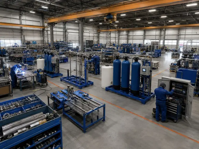
70,500 sqm
21,000 sqm
78
28
Our team carries out full fabrication, pre-assembly, leak testing, and PLC commissioning at our factory. Every multi-tank skid ships with factory hydrostatic test records and a pre-departure PLC sequence run log.
CE-related documentation is reviewed by project scope and configuration. ISO 9001 covers our full manufacturing process. ASME-stamped vessel configurations are available where the destination market or buyer specification requires pressure vessel certification — confirmed at the project review stage. We export to 20+ countries and regions. Custom integration is available for multi-tank systems specified as components within a larger water treatment package.
Project Data Required for Configuration Specification
Send us the following project data. We will return a tank count, grain capacity per vessel, configuration variant recommendation, and rotation schedule basis for your actual operating conditions.
Source water hardness
mg/L CaCO₃ or GPG; include iron content if known.
System flow rate
Peak and average GPM; daily demand profile if variable.
Daily operating hours
Hours in active service; available regeneration window if any.
Downstream application
Boiler, food-grade, pharmaceutical, hotel, cooling tower, laundry, or other.
Output hardness target
Maximum acceptable hardness in mg/L as CaCO₃ at softener outlet.
Inlet pressure and temperature
Measured at the softener skid connection point.
Power supply
Voltage and frequency (e.g., 380V/50Hz, 460V/60Hz).
Destination and certification
CE-related documents and ASME options reviewed by project scope.
Project quantity and timeline
Single or multiple systems; OEM/ODM skid integration; target delivery date.
Related Configuration Routes
For applications where alternating two-vessel coverage between regeneration cycles is sufficient, the single-valve double-tank alternating softener provides continuous soft water output at lower system complexity and capital cost than multi-tank. This is the correct tier for demand profiles below approximately 100 GPM where an overnight regeneration window is reliably available.
When peak flow rate is the primary specification driver and the two-vessel service ceiling is sufficient, the double-valve double-tank parallel softener maximizes service GPM within a two-tank footprint — without the rotation engineering or brine system scale of a triplex system. If your peak demand falls below the duplex parallel service ceiling and site footprint limits a three-tank skid, this is the configuration to review before committing to multi-tank.