
Industrial Ultrafiltration Systems for RO Pretreatment and Process Water Clarity
An industrial ultra filtration system uses hollow fiber membranes to remove suspended solids, turbidity, and biological load before downstream RO or process equipment. We engineer hollow fiber ultrafiltration systems as a configurable pretreatment stage for reverse osmosis and as a standalone membrane barrier for industrial process water clarification. If your feed water carries variable turbidity, biological load, suspended solids, or SDI levels that RO membranes cannot reliably absorb, UF is the stage we add between raw feed and downstream treatment.
What an Industrial Ultrafiltration System Delivers
UF membrane systems reduce suspended solids, turbidity, bacteria, algae, colloids, and high-molecular-weight organics in feed water before a downstream RO system or process equipment. The system operates at low transmembrane pressure through hollow fiber membranes — typically 0.01–0.1 µm pore size for PVDF or PES — that create a consistent physical barrier even when feed-water quality fluctuates seasonally.
What passes through
Clarified permeate moves forward to RO, direct process use, or a downstream storage step. UF does not remove dissolved salts or TDS; if your project requires conductivity control, desalination, or TDS reduction, that function belongs to reverse osmosis downstream.
Why this page starts with feed water
Variable feed-water quality is the first question our engineers ask in export UF projects. A UF skid is not selected only by flow rate; it is selected by what the downstream system must be protected from.
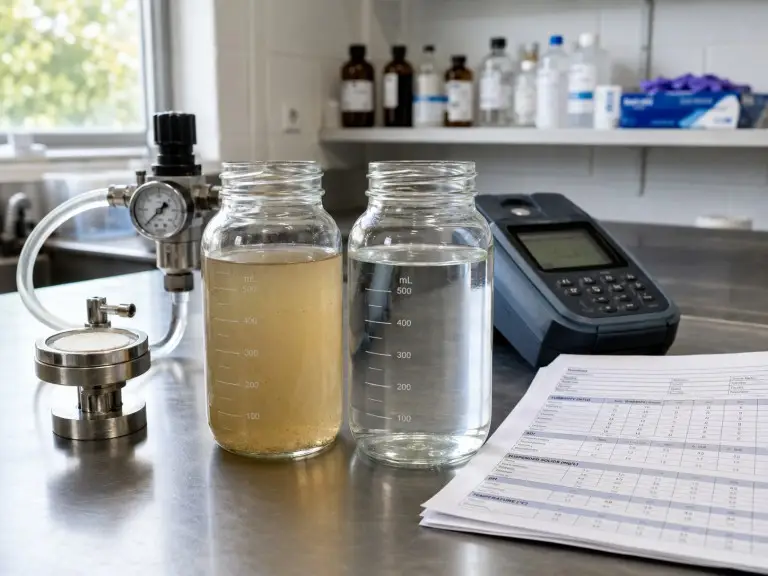
When Your Source Water Requires UF Before RO
UF is the correct pretreatment choice when feed-water conditions exceed what conventional media filtration can handle reliably. When feed SDI spikes above 5 during monsoon season or algae bloom, a fixed-media filter treats average conditions — not the peak events that actually damage downstream RO membranes.
High or Variable Turbidity
Conventional media filters can pass turbidity spikes above 20–30 NTU. UF gives the treatment train a physical membrane barrier rated to 0.01–0.1 µm, so the downstream RO stage is not exposed to every feed-water fluctuation.
Elevated SDI Risk
Feed SDI consistently above 5 shortens RO membrane life and increases chemical cleaning frequency. UF is reviewed when SDI needs to be reduced below 3 for downstream RO feed protection.
Biological Load
Bacteria, algae, and biological particulates accelerate RO biofouling when they move downstream. We review biological loading before deciding between simple prefiltration and UF.
Surface or Seasonal Feed
Surface water and mixed groundwater sources can shift between clear operation and high-turbidity events. UF is considered when pretreatment must remain stable during those events.
Wastewater Reuse Loop
Reclaimed wastewater often carries suspended solids and biological load that RO cannot process directly. UF creates the membrane barrier before the RO reclamation stage.
Microbial Barrier Need
Food, pharmaceutical, electronics, and process-water applications may need a physical microbial barrier at pretreatment. UF with 0.01–0.02 µm pore size provides a physical log-reduction barrier at the pretreatment stage.
When UF is not the right first stage
If the feed water is stable, low-turbidity, and low-biological-load municipal supply, a standard cartridge filter before RO may be technically sufficient. We do not recommend UF for every pretreatment position; we recommend it when the feed conditions justify the membrane stage.
What UF Removes and What It Does Not Remove
UF membranes provide a physical barrier for particles and biological agents above their pore size while allowing water and dissolved species to pass through. This boundary matters because UF and RO solve different separation problems.
UF Removes or Reduces
- Suspended solids and visible particulates
- Turbidity and colloids
- Bacteria and biological cells
- Algae and biological particulates
- Colloidal silica, partial and size dependent
- Viruses at the lower end of the UF pore range, size dependent and not a log-removal guarantee
- High-molecular-weight organic molecules
UF Does Not Remove
- Dissolved salts such as sodium, calcium, magnesium, chloride, and sulfate
- Total dissolved solids or conductivity
- Dissolved heavy metals in ionic form
- Small organic molecules below membrane MWCO
- Dissolved silica in ionic or monomeric form
- Dissolved gases
UF and RO are sequential stages, not substitutes
If your feed has dissolved-salt or TDS targets, the correct system sequence is UF followed by RO, not UF alone. For downstream salt removal, a brackish water reverse osmosis stage handles TDS between 1,000–15,000 ppm, while a seawater desalination system addresses intake salinity above 25,000 ppm.
UF vs. Media Filtration, Cartridge Filtration, and RO
Positioning UF correctly requires knowing what each stage does and what it cannot do. Replacing one stage with another without reviewing feed conditions creates either an overbuilt system or an under-protected RO train.
| Stage | Primary Separation Function | Where It Fits | Relationship to UF |
|---|---|---|---|
| Dual media filtration | Reduces suspended solids and turbidity by depth filtration. | Pre-UF or standalone pretreatment for lower-SDI feeds. | Can reduce membrane loading, but feed spikes may still pass through compared with a membrane barrier. |
| Cartridge filtration | Fine polishing for low-flow and low-particulate streams. | Before RO on clean, low-load feeds. | UF replaces repeated cartridge change-out when flow, turbidity, and biological load justify a membrane stage. |
| Ultrafiltration | Physical barrier for suspended solids, bacteria, turbidity, and biological load. | RO pretreatment or standalone process water clarification. | Provides controlled pretreatment but does not remove dissolved salts. |
| Reverse osmosis | Dissolved salt, TDS, and ionic species reduction. | After UF when conductivity or desalination is required. | RO removes what UF does not; UF protects RO from what RO should not receive. |
Our review boundary. When we review an RO pretreatment inquiry, we check whether the buyer is trying to solve a two-stage problem with one stage. A surface-water feed with variable turbidity and a product-water TDS target usually needs both UF and RO.
How We Place UF in the Water Treatment Train
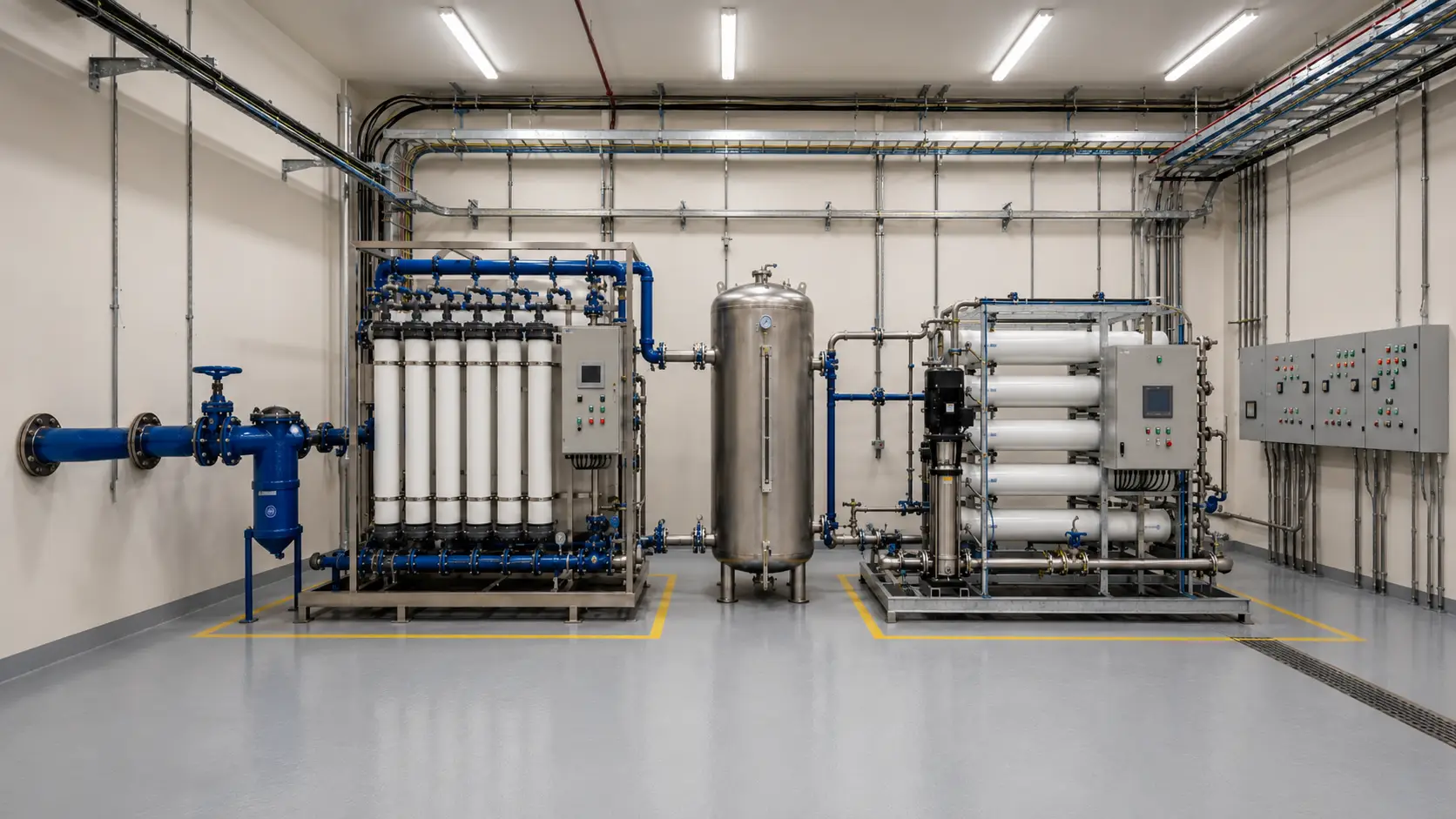
Our UF systems are configured as pressurized hollow fiber skids that connect into a water treatment train upstream of RO or process equipment. Feed pressure, downstream back-pressure, tank sizing, dosing, and connection points are confirmed during system review.
Raw Feed Water
Source water is checked against visible debris, seasonal variation, and inlet pressure before we place the UF skid.
Coarse Screening / Strainer
A strainer or screen is reviewed when the feed carries debris that should not reach the UF modules.
Pre-Dosing
Coagulant or antiscalant is selected from feed behavior, not added as a default accessory.
UF System
Hollow fiber membrane modules retain suspended solids and biological load before downstream treatment.
Permeate Tank
UF permeate storage is balanced with backwash water reserve and downstream demand.
Downstream RO System
UF permeate moves to RO when dissolved-salt reduction is required.
Direct Process Use
For clean process-water uses, UF may serve as the final clarification stage without a downstream RO stage.
Backwash return
UF permeate or air-assisted water reverses through the membrane on a timed or TMP-triggered cycle. Backwash frequency and duration are set during commissioning against actual feed behavior — a clean surface-water feed and an algae-loaded intake do not share the same recovery logic.
CIP circuit
Chemical clean-in-place recovers membrane flux when TMP trends upward and backwash alone is no longer sufficient. Chemical selection, concentration, and contact time are matched to the dominant fouling type rather than copied from a generic package.
Concentrate discharge
The reject stream carrying concentrated solids is routed to drain or to a recovery circuit according to site requirements. We check discharge routing before finalizing the skid because local discharge constraints can affect pretreatment layout and water balance.
UF System Configuration Variables
Each ultrafiltration water treatment system we build is specified to the project’s feed-water conditions and downstream requirements — surface-water UF at 40–80 LMH flux operates under different fouling assumptions than a seawater-intake UF sized at 50–70 LMH with higher backwash frequency.
Membrane Material for Your Ultra Filtration System
PVDF is our standard selection for many industrial and export UF projects because it offers higher chemical tolerance, a wider pH operating window, chlorine resistance, and longer operating life under aggressive CIP cycles. PVDF tolerates free chlorine up to ~200 ppm during CIP; PES is typically limited to ~100 ppm but may offer higher flux in clean-feed applications.
Flow Direction
Outside-in operation feeds water around the hollow fiber bundle and tolerates higher suspended solids, which is why we review it for variable-turbidity surface water and high-SS feeds. Inside-out operation feeds through the lumen and is used for cleaner, more consistent water where controlled flux distribution is the priority.
Backwash Logic
Automated backwash cycles push permeate or air-assisted water reverse through the membrane to recover flux. Cycle intervals are reviewed against real feed conditions so the system avoids both wasted water and unrecoverable fouling. Intervals set too short waste water and energy; intervals set too long allow fouling to accumulate beyond normal recovery.
CIP / Clean-in-Place
When backwash no longer restores permeate flux and TMP elevation persists, we specify chemical CIP using acid, alkali, oxidant, or combined cleaning chemistry according to the dominant fouling type. Biological, inorganic scaling, and organic fouling require different cleaning chemistry, so we estimate the requirement from feed-water characterization and confirm the protocol during commissioning.
Control System
PLC-based control can include TMP monitoring, backwash triggering, CIP interlocks, flow-rate control, and fault alarms. SCADA connection and remote monitoring are confirmed for larger or multi-skid installations.
| Variable | Engineering Reference | Project Status |
|---|---|---|
| Membrane pore size | 0.01–0.1 µm, with about 0.03 µm common for PVDF hollow fiber | General reference, confirmed by application |
| MWCO | 100–200 kDa | General engineering reference |
| Operating TMP | 0.1–0.3 MPa typical service | Confirmed during design review |
| Feed suspended solids | Outside-in reviewed above ~50 mg/L SS; inside-out typically below ~30 mg/L | Variable, based on water analysis |
| Feed turbidity | Reviewed when feed turbidity exceeds ~20 NTU or spikes above 100 NTU seasonally | Confirmed during feed-water review |
| Output SDI | Design target SDI < 3 for downstream RO feed (actual depends on feed and fouling) | Not a fixed guarantee; reviewed per feed |
| Backwash cycle | Often reviewed in a 20–60 minute operating interval range | Set during commissioning |
| Backwash water balance | Includes permeate flow plus backwash volume | Reviewed for inlet pipe sizing, pre-UF storage, and site water balance |
| Membrane material | PVDF or PES | Project-specific selection |
| Flow direction | Outside-in or inside-out | Matched to feed load and module configuration |
| Operating pH | PVDF typically 1–11; PES typically 2–12 (CIP range may differ) | Confirmed per project and CIP plan |
| Temperature | 1–40 °C typical; flux correction applied above 25 °C and below 15 °C | Confirmed from site conditions |
| Service life | Depends on feed quality, flux, backwash, and CIP management | Not a fixed commitment |
| Capacity range | 1–200 m³/h per skid (multi-skid parallel for larger capacity) | Confirmed after flow and redundancy review |
| Design flux | 40–80 LMH typical for surface water; 60–120 LMH for municipal pre-treated feed | Adjusted for temperature, fouling factor, and membrane model |
| Recovery rate | 90–95% typical design target (balance depends on backwash volume) | Confirmed with water balance calculation |
| Skid frame material | SS304 standard; SS316L for high-chloride, coastal, or food-grade environments | Selected from feed chemistry and site conditions |
| Electrical supply | 380V/50Hz standard export; 415V/50Hz, 460V/60Hz, 220V/60Hz available | Confirmed to destination country grid standard |
| PLC platform | Siemens S7-1200 standard; Allen-Bradley, Mitsubishi, Schneider available on request | Confirmed from buyer specification or regional preference |
The values above are Hiju preliminary design targets for hollow fiber UF pretreatment projects. Final limits depend on membrane model, feed-water analysis, recovery target, temperature, fouling projection, and backwash/CIP design.
Common Review Mistakes We Check Before UF Sizing
Each ultrafiltration unit is clearly bounded in what it removes. When buyer expectations extend beyond those boundaries, or when sizing is applied without feed-water review, the system will underperform against the specification.
Expecting UF to Control TDS
UF membranes pass dissolved salts. If a project calls for TDS reduction or conductivity control, RO downstream performs that function. Quoting UF alone for a two-stage problem creates a mismatch that has to be corrected after installation.
Treating Output SDI as Feed-Independent
SDI output depends on feed SDI, pore size, flux, fouling rate, and backwash effectiveness. We do not quote a fixed SDI output before reviewing the feed-water data.
Using One Membrane Configuration for All Feeds
Outside-in and inside-out configurations have different suspended solids tolerance profiles. Configuration selection is made against your feed-water analysis, not from a standard template.
Ignoring Backwash Water Demand
UF systems use permeate for backwash. Inlet pipe sizing, pre-UF storage, and total water balance must account for permeate flow plus backwash volume.
Assuming CIP Is Fixed at Quotation
CIP chemistry and frequency depend on biological, inorganic, or organic fouling type. We estimate the cleaning requirement during design and confirm the protocol during commissioning.
Where We Configure UF Systems
Our UF systems are configured across industrial and export water treatment applications, from RO pretreatment on variable-source feeds to standalone process-water clarification.
RO Pretreatment for Surface, Brackish, and Seawater Sources
When the downstream system is an industrial reverse osmosis system, UF protects membranes from suspended solids, biological fouling, and SDI elevation that would otherwise shorten membrane life and increase chemical cleaning frequency. We configure each UF skid to match the downstream RO permeate quality requirement, flow rate, and pretreatment boundary. Surface water, seasonally variable groundwater, and seawater intake sources are the feeds where UF pretreatment delivers the clearest long-term operating advantage.
Food and Beverage Process Water
Food and beverage manufacturing requires process water controlled for microbial load, turbidity, and particulate content, often within food-grade material and skid-construction expectations. We size UF units with attention to skid material compatibility, cleanability, and CIP cycle requirements specific to food-grade environments.
Bottled water plants and food-grade water systems →Pharmaceutical and Electronics Pretreatment
Pharmaceutical, semiconductor, and electronics processes require physical pretreatment control upstream of EDI, double-pass RO, or high-purity polishing. UF protects downstream membranes and ion exchange resin from biological and colloidal fouling that conventional prefiltration cannot reliably control. Final compliance must be confirmed against the user’s process specification, validation protocol, and applicable local standard.
Deionized water filtration system for pharma and electronics →Municipal and Industrial Clarification
Municipal potable water intakes from surface sources often pair UF with a downstream commercial RO water filter system when both turbidity control and TDS reduction are required. Cooling towers, boiler feed circuits, and plant utility loops also require turbidity and biological load control, and we review UF when a consistent physical membrane barrier is needed at the treatment stage.
Wastewater Reclamation Pretreatment
In UF to RO reclamation loops, UF creates the membrane barrier that protects RO from the biological and suspended solids load typical of secondary-treated effluent. Feed conditions for reuse streams vary significantly in fouling potential, so we review feed-water quality data before confirming the UF design.
Why Hiju for Export UF Projects
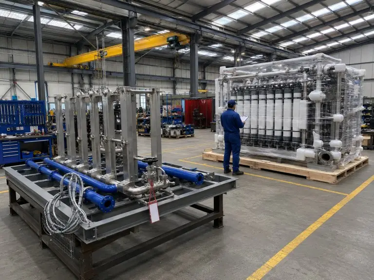
Our UF systems are manufactured at our Qingdao facility — 70,500 m² total site area with a 21,000 m² production workshop — where 28 engineers and 78 technicians handle feed-water review, skid fabrication, inspection, and factory acceptance for export water treatment projects.
Certification and Export Reach
Our factory holds CE and ISO 9001 certifications; ASME U-stamp for pressure-vessel components is available on request when specified in the purchase order. Certification scope is confirmed during order review. We export to 20+ countries including Southeast Asia, the Middle East, Africa, South America, and Central Asia. Voltage, packing, documentation, and site-environment requirements are confirmed before production.
OEM and ODM Capability
For integrators, EPC contractors, and distributors, we review custom skid dimensions, private-label control panels, branded documentation packages, and adapted factory acceptance requirements. OEM/ODM scope affects drawing review, control-panel language, documentation format, packing, and inspection records.
What We Need for a UF System Review
To give you a UF system recommendation rather than a generic quotation, we need feed-water parameters before specifying equipment. The more you share at inquiry stage, the more specific our review can be.
Feed Water
- Feed source: surface, groundwater, municipal, process, or reuse water.
- Feed turbidity in NTU, measured or estimated, with seasonal variation noted.
- Feed SDI, or turbidity and suspended solids data if SDI is not measured.
- Feed suspended solids in mg/L if measured.
- Feed TDS or conductivity when UF is upstream of RO.
- pH, temperature range, biological load, algae season, oil trace, or unusual contaminants.
System Requirements
- Required permeate flow rate in m³/h or GPM.
- Downstream system type: RO, direct process use, or reuse loop.
- Output SDI or turbidity target if specified by downstream equipment.
- Installation environment: indoor, outdoor, or containerized.
- Ambient temperature range and site service conditions.
- Certifications required for your market or procurement process.
Project Context
- New installation or retrofit into an existing treatment train.
- OEM/ODM requirement, custom skid dimensions, private label, or branded control panel.
- Destination country, import requirements, and project timeline.
- Local regulatory or documentation requirements if applicable.
- Preferred contact method: WhatsApp, Email, or online inquiry form.
Send feed-water data before price comparison
We review source-water conditions, flow, downstream system type, and installation constraints before confirming a UF specification; partial data is workable, but it usually produces a wider estimate range until the missing values are confirmed.